Configuration
5-28 7SJ62 Manual
C53000-G1140-C121-1
Any new user defined information is also shown in the display once loaded into the
relay from DIGSI
®
4.
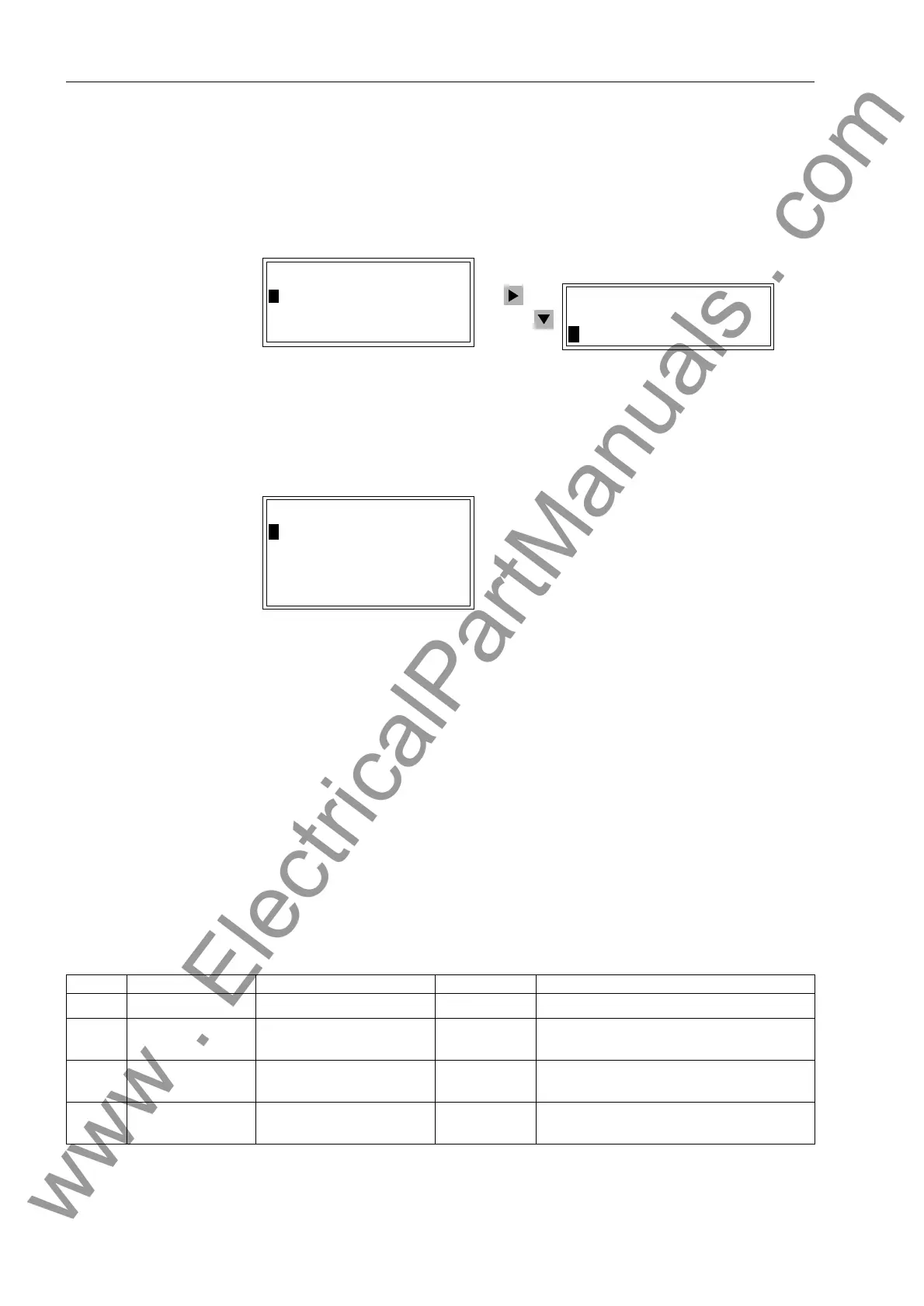
When selecting the 0$6.,1*,2 menu, either binary inputs, LEDs, or binary out-
puts may be selected. Selection of binary inputs is illustrated in Figure 5-27.
Figure 5-27 Reading the Configuration in the Display
Information regarding a binary input may be displayed by using the navigation keys to
select the binary input. See Figure 5-28.
Figure 5-28 Selection of Binary Input 2
In Figure 5-28, information is displayed regarding binary input 2. The display for binary
input 2 indicates that it is configured as the acknowledgment of LEDs using a single
point indication with voltage active (High). The present conditions of binary input 2 is
also given as 0 (not active). If binary input is active, a 1 is displayed.
Assignment of LEDs may be indicated at the relay, itself, using a replaceable labeling
strip with plain text on the front panel located, directly next to the LEDs.
Preset Configura-
tions
The pre-set configurations of the binary inputs and outputs are shown in the overview
circuit figures (Appendix A.2).
The preset configurations for the LED displays upon relay delivery are listed in the fol-
lowing table.
0$6.,1*,2
!%LQDU\,QSXWV²!
!/('²!
%LQDU\2XWSXWV²!
%,1$5<,13876
!%LQDU\,QSXW²!²
!%LQDU\,QSXW²!²
%,1$5<,1387
!!5HVHW/('63+
6WDWXVDW7HUPLQDO
Table 5-4 Preset Configuration for LED Display
LED Descriptive Text Brief Text Message # Comments
LED 1 Relay Tripped Relay Tripped 511 One the protective functions initiated a trip.
LED 2 Pickup Phase A Non-Directional Phase A
Directional Phase A
Pickup by Aφ Element
LED 3 Pickup Phase B Non-Directional Phase B
Directional Phase B
Pickup by Bφ Element
LED 4 Pickup Phase C Non-Directional Phase C
Directional Phase C
Pickup by Cφ Element
www . ElectricalPartManuals . com

 Loading...


