Functions
6-1457SJ62 Manual
C53000-G1140-C121-1
Result As results of the fault location, the following results are displayed or obtained using
DIGSI
®
4:
− One or more short circuit paths from which the fault reactance was derived.
− One or more reactance’s per phase in Ω secondary.
− The fault distances, proportional to the reactance’s, in km or miles of line, converted
on the basis of the line’s predetermined reactance (entered at address or
, see Subsection 6.1.3).
Note:
The distance result, in miles or kilometers, can only be accurate for homogenous
line sections. If the line is made up of several sections with different reactance’s, then
the reactance derived by the fault location can be evaluated for a separate calculation
of the fault distance. For transformers and motors, only the reactance result, not the
distance result, is significant.
6.15.2 Setting The Functional Parameters
General The calculation of fault distance will only take place if address is set to (QDEOHG.
If the fault locating function is not needed, then address should be set to 'LV
DEOHG.
Initiation Normally the fault location calculation is started when a protective element initiates a
trip signal. However, address 67$57 is set to 3LFNXS, fault location can be ini-
tiated just by the pickup of a protective element. If address 8001 is set to 7ULS, then
via a binary input, fault location can still be initiated just by the pickup of a protective
element.
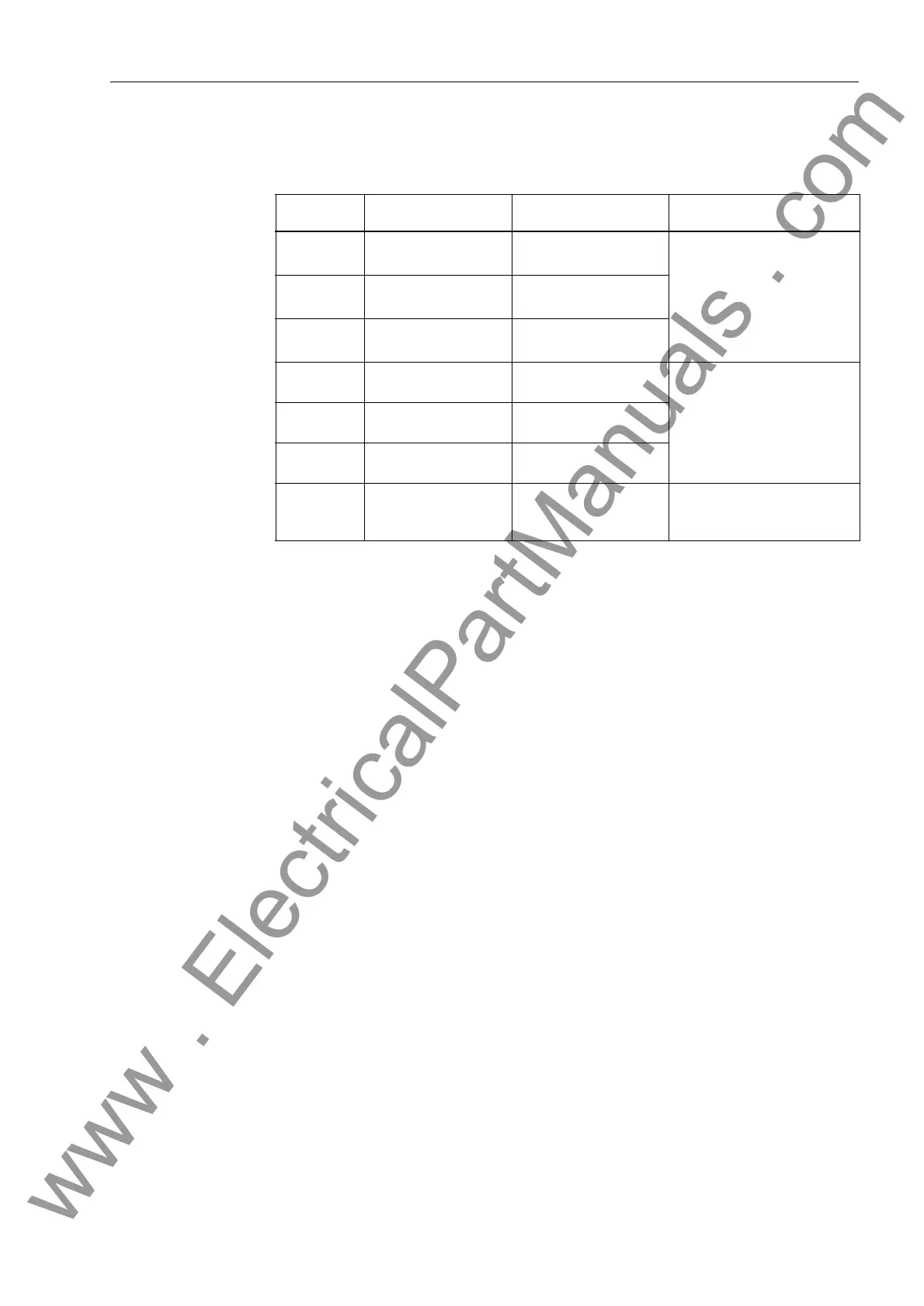
Table 6-4 Selection of Paths to be Reported for Open-Delta Connected Voltage Transform-
ers
Pickup Possible Paths Evaluated Paths Notes
A A–B, C–A
Least φ − φ
The least φ-φ path is dis-
played.
B A–B, B–C
Least φ − φ
C C–A, B–C
Least φ − φ
A, B A–B A–B
The appropriate
φ-φ path is
displayed.
B, C B–C B–C
A, C C–A C–A
A, B, C A–B, B–C, C–A Least
φ-φ path The least φ-φ path is dis-
played.
www . ElectricalPartManuals . com

 Loading...


