Functions
6-1017SJ62 Manual
C53000-G1140-C121-1
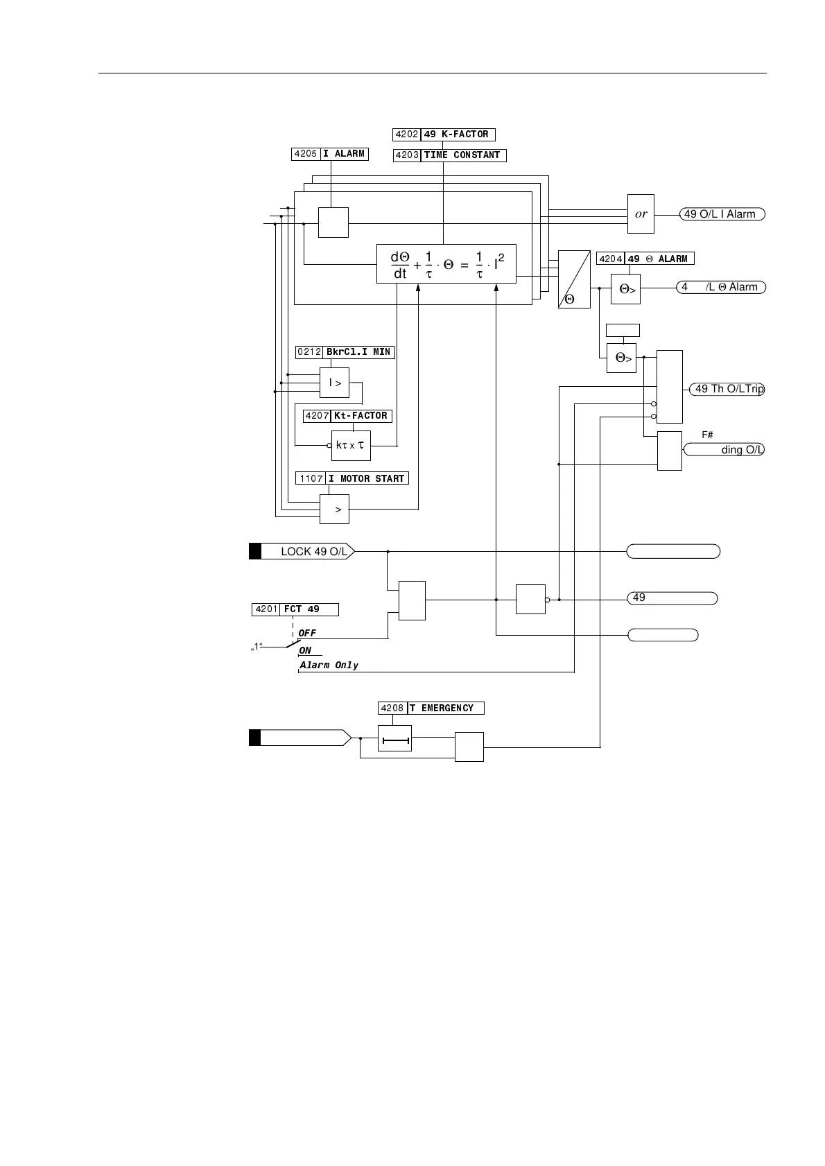
Figure 6-45 Logic Diagram for Thermal Overload Protection
6.9.2 Programming Settings
General Thermal overload protection is only effective and accessible if address was set
to (QDEOHG during configuration of protective functions. If the thermal overload pro-
tection is not required, address should be set to 'LVDEOHG.
Transformers and cable are prone to damage by overloads which last for an extended
period of time. For this reason, fault protection elements such as the directional and
non-directional overcurrent elements should not be used to protect against overload.
%NU&O,0,1
Θ
$/$50
7(0(5*(1&<
,0272567$57
,$/$50
21
2))
„1“
)&7
or
49 O/L I Alarm
I >
I >
.W)$&725
kτ x τ
dΘ
dt
--------
1
τ
---
Θ⋅
+
1
τ
---
I
2
⋅
=
Θ>
Θ>
49 Th O/LTrip
49 O/L Θ Alarm
Θ
max
Aφ
CB Closed
I
a
&
I
b
I
c
>BLOCK 49 O/L
49 O/L ACTIVE
or
>EmergencyStart
T0
$ODUP2QO\
I >
Θ = const.
Θ = 0
49 O/L BLOCK
F# 1515
F# 1516
F# 1521
F# 1512
F# 1513
F# 1503
F# 1507
7,0(&2167$17
.)$&725
or
49 O/L OFF
F# 1511
or
100 %
&
49 Winding O/L
F# 1517
www . ElectricalPartManuals . com

 Loading...


