Appendix
A-697SJ62 Manual
C53000-G1140-C121-1
A.8 Default Settings
Some CFC Charts are already supplied with the SIPROTEC
®
device:
Device and System
Logic
:
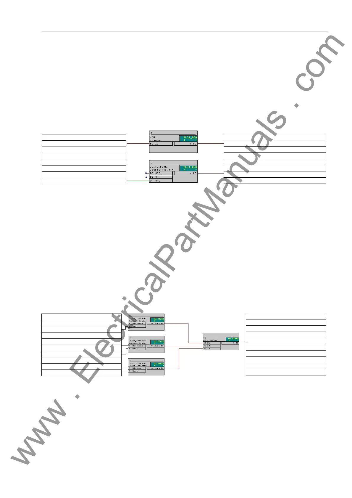
Figure A-16Device and System Logic
Set points Using modules on the running sequence “measured value processing”, a low current
monitor for the three phase currents is implemented. The output message is set high
as soon as one of the three phase currents falls below the set threshold:
Figure A-17 Undercurrent monitoring 37-1
IN: Device, General SP
OUT: Control Device Block Data IntSP
IN: Control Device GndSwit. DP
OUT: Device, General Feeder gnd IntSP
IN: Set points 37-1 LV
IN: Measurement Ia = MV
IN: Set points 37-1 LV
IN: Measurement Ib = MV
IN: Set points 37-1 LV
IN: Measurement Ic = MV
OUT: Set points SP. 37-1
alarm OUT
www . ElectricalPartManuals . com

 Loading...


