Functions
6-8 7SJ62 Manual
C53000-G1140-C121-1
Confirmation Each entry may be confirmed by clicking $SSO\. Valid values are accepted automat-
ically when another field is selected.
The final acceptance of a modified setting takes place once setting modification mode
is exited (see below “Exiting the Setting Modification Mode”).
The dialog box may be closed by clicking 2.. Once closed, another function may be
selected for setting modification, or the user can exit setting modification mode.
Exiting the Setting
Modification Mode
In order to transfer the modified setting values to the relay, the user should click on
',*6, → 'HYLFH. The user will be prompted for Password No. 5. After entering the
password and confirming with 2., data is transferred to the relay where modifications
become effective.
6.1.1 Power System Data 1
The device requires certain basic data regarding the protected equipment, so that the
device will be compatible with its desired application. Phase sequence data, nominal
system frequency data, CT&PT ratios and their physical connections, as well as,
breaker operating times and minimum current thresholds are selected in the 3RZHU
6\VWHP'DWD display.
To modify these settings from the front of the device, the user should press the key
and wait for the 0$,10(18 to appear. From the 0$,10(18, the user should use the
key to select 6HWWLQJV, and then use the key to navigate to the 6(77,1*6
display. To obtain the 36\VWHP'DWD display, the user should use the key to
select 36\VWHP'DWD in the 6(77,1*6 display, and then press the key.
To modify settings associated with 3RZHU6\VWHP'DWD using DIGSI
®
4, the user
should double-click 6HWWLQJV, and then 3RZHU6\VWHP'DWD, and the desired
selection options will be displayed.
Polarity of Current
Transformers
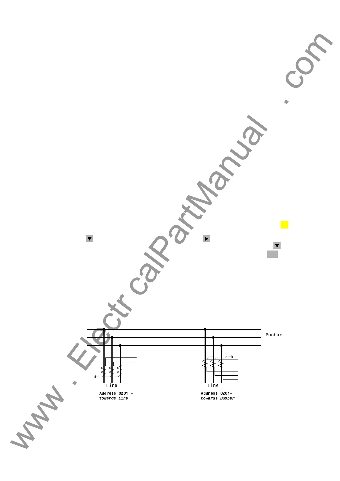
At address &76WDUSRLQW, the polarity of the wye-connected current trans-
formers is specified (see Figure 6-8 for options). Modifying this setting also results in
a polarity reversal of the ground current inputs I
N
or I
NS
.
Figure 6-8 Current Transformer Polarity
MENU
ENTER
I
A
I
B
I
C
I
G
I
A
I
B
I
C
I
G
$GGUHVV
$GGUHVV
%XVEDU
/LQH /LQH
WRZDUGV/LQH WRZDUGV%XVEDU
www . ElectricalPartManuals . com

 Loading...


