Functions
6-797SJ62 Manual
C53000-G1140-C121-1
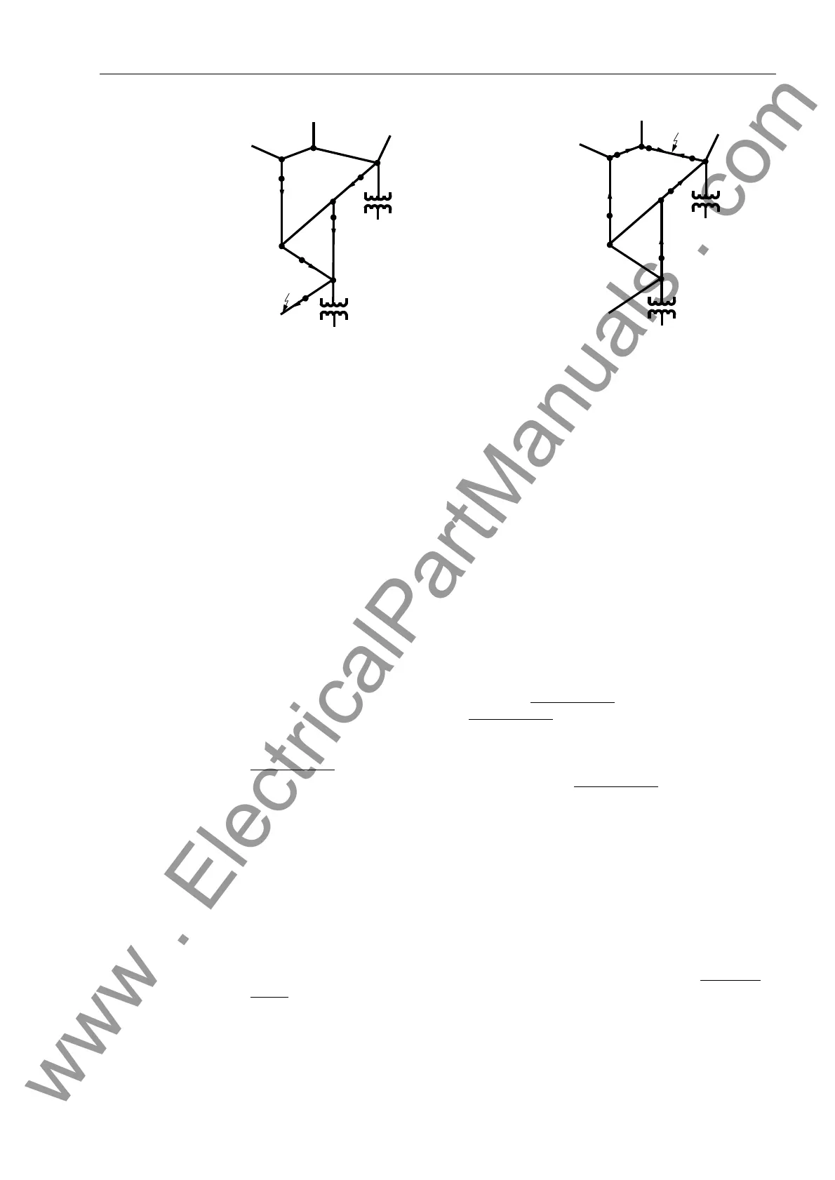
Figure 6-37 Location of Ground Connection based on Direction Indicators in a Looped Sys-
tem
6.6.2 Programming Settings
General Settings During configuration of protective functions, address 6HQV*QG)DXOW should
be set to 'HILQLWH7LPHRQO\ if the inverse characteristic is not required, 8VHU
'HILQHG3LFNXS&XUYH if both a definite time and inverse time characteristic are
required, and 'LVDE OHG if the function is not required at all.
Also, during configuration, address 97&RQQHFWLRQ determines how the volt-
age transformers are connected (phase-to-ground or phase-to-phase), and addresses
9SK9GHOWD and &71V&73K contain the conforming factors for zero
sequence ground voltage and the zero sequence current inputs.
Sensitive ground fault detection may be switched 21, 2)), or to 0HVVDJH2QO\, at
address 6HQV*QG)DXOW. If sensitive ground fault protection is switched 21,
both tripping and message reporting is possible.
Angular Error
Compensation
Addresses through only apply to compensated
systems which utilize Pe-
tersen coils. Since the utilization of compensated
systems is primarily limited to Euro-
pean practices, a detailed explanation of these settings is beyond the scope of this
particular instruction manual. In the rare event that this protective relay is utilized in a
compensated
system, the reader should contact Siemens Power T&D for more infor-
mation regarding application of the 7SJ62 relay in a compensated
system.
Determination of
the Phase with a
Ground Connection
The phase connected to ground may be identified in an ungrounded system, if the de-
vice is supplied by three voltage transformers connected in a grounded-wye configu-
ration. The phase whose voltage lies below the minimum voltage setting at address
93+0,1 is identified as the phase connected to ground as long as the other
two phase voltages simultaneously exceed the maximum voltage setting at address
93+0$;. The setting at address must be set less than the minimum al-
lowable phase-to-ground voltage. A typical setting for this address would be 40 V. The
maximum voltage setting at address must be greater than the minimum allow-
able phase-to-ground voltage, but less than the minimum phase-to-phase voltage. For
V
N
= 100 V, approximately 75 V is a typical setting. These settings have no signifi-
cance in a grounded system.
Displacement Volt-
age V
0
or 3V
0
The pickup due to displacement voltage is set at address 9*1' if V
0
is
measured or address 9*1' is 3V
0
is calculated. Pickup of the voltage el-
www . ElectricalPartManuals . com

 Loading...


