Installation and Commissioning
8-16 7SJ62 Manual
C53000-G1140-C121-1
RS 485
Termination
The RS 485 interface is capable of half-duplex mode with the signals A/A’ and B/B’
with a common relative potential C/C’ (DGND). Verify that only the last device on the
bus has the terminating resistors connected, and that the other devices on the bus do
not. The jumpers for the terminating resistors are on the interface card mounted on the
CPU board. Refer to Figures 8-7 to 8-9.
If the bus is extended, make sure again that only the last device on the bus has the
terminating resistors switched-in, and that all other devices on the bus do not.
Time
Synchronization
Interface
Either 5 VDC, 12 VDC or 24 VDC time synchronization signals can be processed if the
connections are made as indicated in Table
8-8.
Optical Fibers Signals transmitted via optical fibers are unaffected by interference. The fibers guar-
antee electrical isolation between the connections. Transmit and receive connections
are shown with the symbols for transmit and for receive.
The normal setting for the optical fiber interface is ”Light off.” If this setting is to be
changed, use the operating program DIGSI
®
4, as described in Section 5.5.
8.2.2 Substation Connections
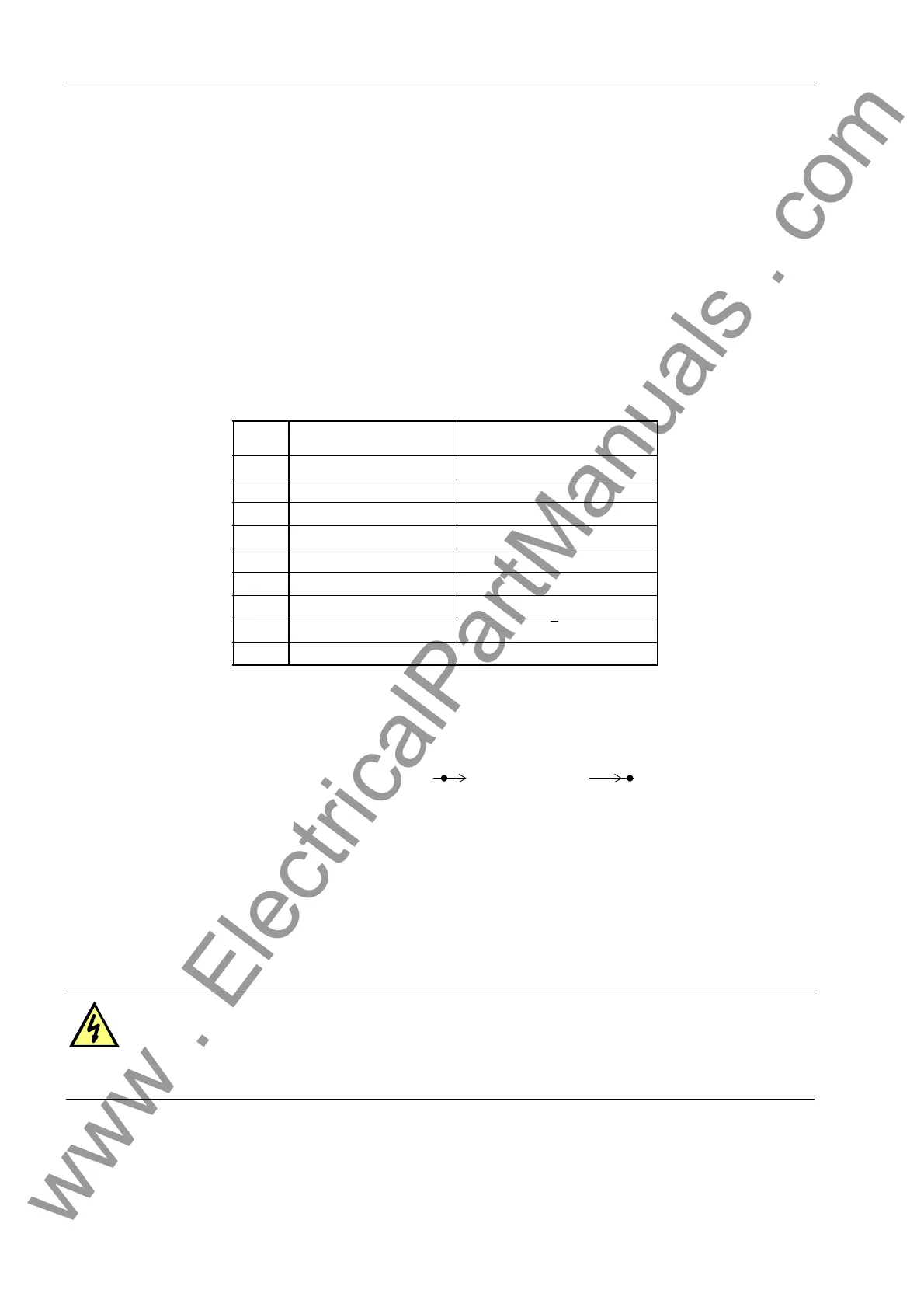
Table 8-8 Pin-assignments for the D-subminiature port of the Time Synchronization
Interface
Pin-
No.
Designation Signal Meaning
1 P24_TSIG Input 24 V
2 P5_TSIG Input 5 V
3 M_TSIG Return Line
4 ––
5 Shield Shield Potential
6– –
7 P12_TSIG Input 12 V
8– –
9 Shield Shield Potential
Warning!
The following procedures are carried out with dangerous voltages present. Therefore,
only qualified people who are familiar with and adhere to the safety procedures and
precautionary measures shall perform the procedures.
www . ElectricalPartManuals . com

 Loading...


