Installation and Commissioning
8-237SJ62 Manual
C53000-G1140-C121-1
.
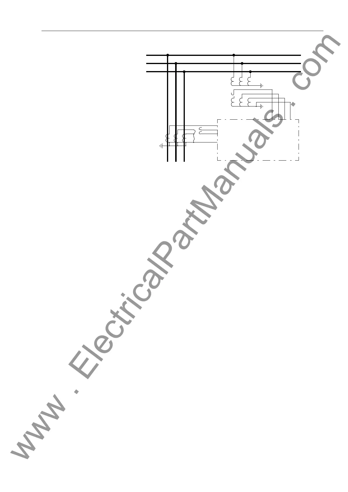
Figure 8-12 Polarity Testing for I
Ns
, Example with Current Transformers Configured in a Hol-
mgreen-Connection (VTs Wye-Connected)
Check the directional data. The messages in the annunciation must contain at least
the message “JURXQGFRQQHFWLRQIRUZDUG” and a pickup message (“1V!21”).
See also Sub-section 6.6.1.3. With an incorrect directional indication “JURXQGFRQ
QHFWLRQUHYHUVHG” or a missing pickup message, a reversal of the voltage connec-
tions of the e-n winding or of the ground current path might exist. With the indication
“JURXQGFRQQHFWLRQXQGHILQHG”, the ground current magnitude is probably too
low. If the pickup message is missing completely, the measured ground current is too
low. If there are no indications whatsoever, then possibly the pickup values for 3V
0
un-
der Address or Address (²9*1') have not been reached.
Correct all connections. Change all of the settings that were modified for testing back
to the valid settings.
8.3.4 Testing the Reverse Interlocking Scheme (if applicable)
This testing causes trip contacts of the 7SJ62 to close. If tripping of the relevant circuit
breakers and primary interrupting devices is to be avoided, the 7SJ62 trip contacts
must be isolated. Proper backup relaying should exist.
An operational check of the reverse interlocking scheme might cause tripping by the
protective relays that block the 7SJ62 (depending on the procedure used). If the block-
ing relays will trip, the trip contacts that control primary interrupting devices must be
isolated if the devices are not to be operated. Again, proper backup relaying should
exist.
Simple methods of testing and operational checking a reverse interlocking scheme are
illustrated with an example. In this example, the 50-2 element and the 50N-2 element
of the 7SJ62 are employed in a reverse interlocking scheme that provides bus protec-
Bus
Line
A
B
C
7SJ62
I
a
I
c
I
b
I
Ns
V
a
V
b
V
c
V
n
www . ElectricalPartManuals . com

 Loading...


