Installation and Commissioning
8-22 7SJ62 Manual
C53000-G1140-C121-1
sured values. Messages from the measured-values supervision should be ignored
during this testing.
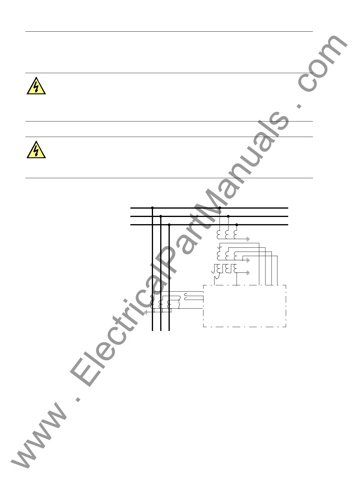
Figure 8-11 Polarity Testing for I
Ns
, Example with Current Transformers Configured in a Hol-
mgreen-Connection (VTs with Broken Delta Connection — e-n Winding)
Directional Testing
for a Grounded Net-
work
To establish 3V
0
(a displacement voltage), the connection of one VT winding is re-
moved from the device. In Figure 8-11, the open delta VTs are modified so that only
V
b
and V
c
are connected to the inputs V
e-n
of the device. Alternatively, V
a
from the
wye-VTs can be disconnected. If no connection for V
Ns
(Ve-n connection) is foreseen,
the secondary side of the corresponding phase can be disconnected as shown in Fig-
ure 8-12. The device receives only the current from the phase where the associated
voltage connection at the device is missing. If the line current is in-phase or lagging
the voltage (resistive or resistive-inductive load), the same current-voltage relation-
ships exist for the device in this test simulation as during a phase-ground fault in the
direction of the line.
DANGER!
Primary measurements must only be carried out on disconnected and grounded
equipment of the power system. Danger to life exists even on disconnected
equipment because of capacitive coupling from other energized equipment of
the power system!
DANGER!
Working on measurement transformers requires the highest precautions!
Short-circuit current transformers before any current connections to the device
are opened!
Bus
Line
A
B
C
e
n
7SJ62
I
a
I
c
V
e
I
b
V
n
I
Ns
V
a
V
b
V
c
V
n
(alternatively, dis-
connect here)
www . ElectricalPartManuals . com

 Loading...


