Functions
6-1277SJ62 Manual
C53000-G1140-C121-1
6.13.2 Programming Settings
General The breaker failure protection function is only effective and available if address
%5($.(5)$,/85( is set to (QDEOHG. If the breaker failure function is not required,
then address should be set to 'LVDEOHG.
Criteria Address &KN%5.&217$&7 establishes whether or not a breaker auxiliary
contact is used, via a binary input, to detect the position of a circuit breaker. If address
is set to 21, then both the current flow through the circuit breaker and the posi-
tion of the circuit breaker auxiliary contact are used to ascertain the position of the cir-
cuit breaker. If address is set to 2)), only the current flow through the circuit
breaker is used to indicate the position of the circuit breaker.
The current flow monitoring setting programmed at address applies to all three
phases, and should be selected such that it is at least 10 % below the smallest fault
current the circuit breaker would interrupt when responding to trip signals initiated by
protective relays. The setting at address should not be set too low, otherwise,
the danger exists that equalization processes in the current transformer secondary cir-
cuit could lead to extended drop out times under conditions of extremely high current.
In addition, it should be noted that other protection functions depend on the current
flow monitoring settings as well (e.g. voltage protection, overload protection, and re-
starting block for motors).
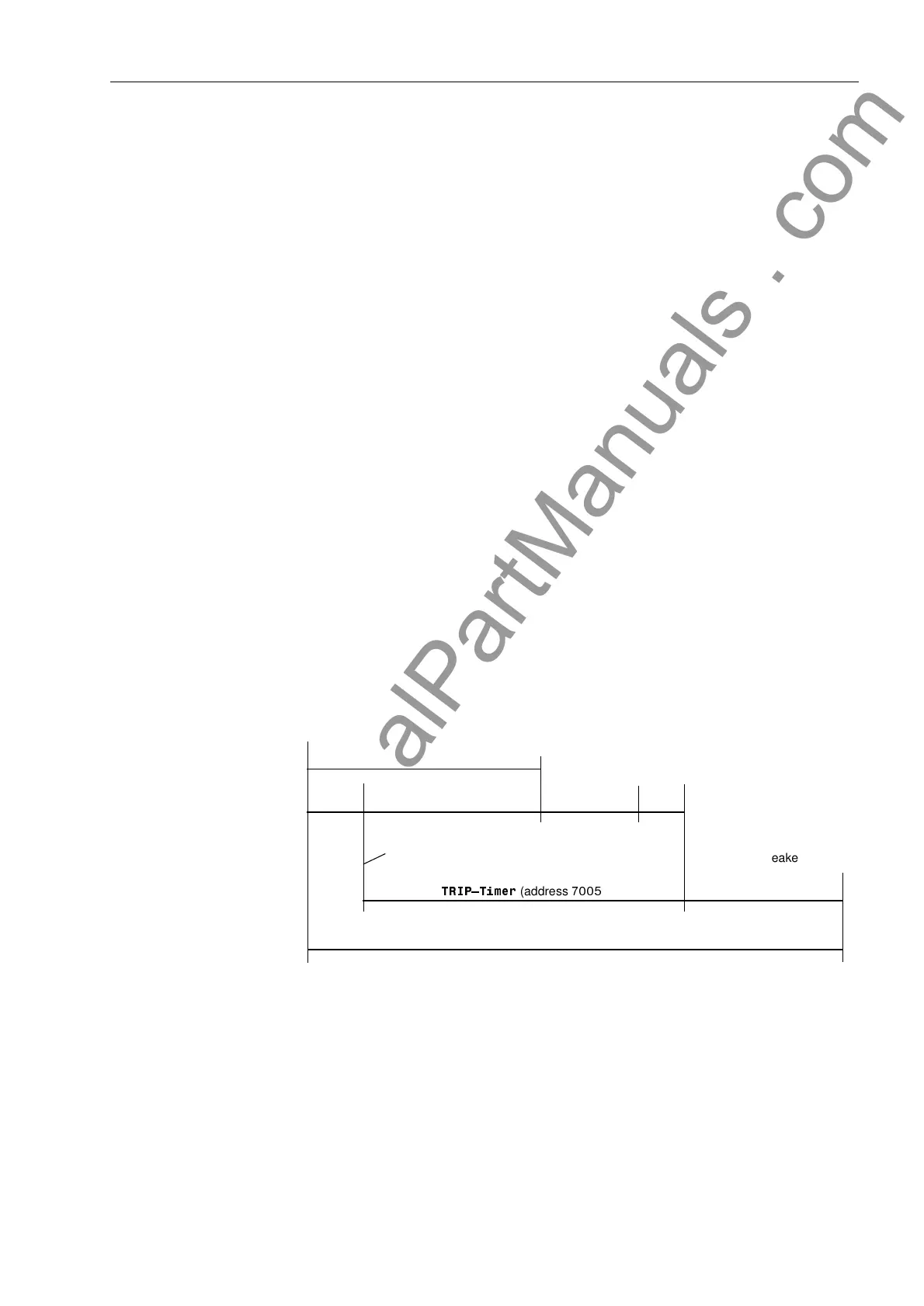
Time Delay The breaker failure time delay setting is entered at address 75,37LPHU. This
setting should be based on the circuit breaker interrupting time plus the dropout time
of the current flow monitoring element plus a safety margin. Figure 6-55 illustrates the
timing of a typical breaker failure scenario.
Figure 6-55 Time Chart for Typical Breaker Failure Operation
Normal Fault Clearing Time
Trip.
Time
Fault Occurs
Breaker Interrupting Time
Current Flow
Monitoring
Drop Out Time
Safety
Time
Breaker Failure
Pickup
Breaker Failure Time Delay
75,3²7LPHU
(address
)
Backup Breaker
Interruption Time
(approx.)
Total Fault Clearing Time for Breaker Failure Condition
www . ElectricalPartManuals . com

 Loading...


