Functions
6-152 7SJ62 Manual
C53000-G1140-C121-1
Address %$/$1&(9²/,0,7 determines the limit voltage (Phase-to-Phase),
above which the voltage symmetry monitor is effective (see also Figure 6-63). Address
%$/)$&7259 is the associated symmetry factor; that is, the slope of the
symmetry characteristic curve (Figure 6-63).
Address %$/$1&(,/,0,7 determines the limit current, above which the cur-
rent symmetry monitor is effective (see also Figure 6-62). Address %$/)$&
725, is the associated symmetry factor; that is, the slope of the symmetry charac-
teristic curve (Figure 6-62).
Address Σ,7+5(6+2/' determines the limit current, above which the current
sum monitor (see Figure 6-61) is activated (absolute portion, only relative to I
N
). The
relative portion (relative to the maximum conductor current) for activating the current
sum monitor (Figure 6-61) is set at address Σ,)$&725.
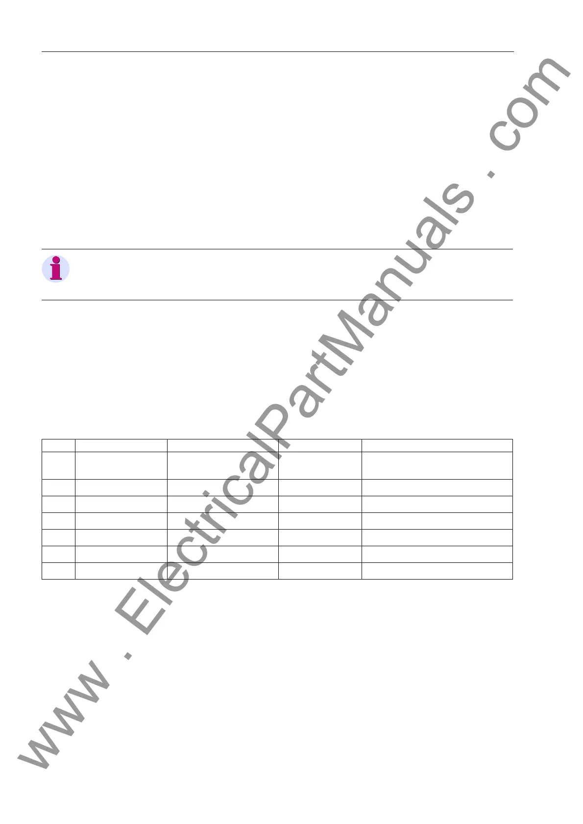
6.17.2.1 Settings for Measured Values Monitoring
In the list below, the setting ranges and default setting values for current-based set-
tings are for a device with a nominal current rating I
N
= 5 A. For a nominal current rat-
ing I
N
= 1 A, divide the Setting Options values and Default Setting values by 5. Con-
sider the current transformer ratios when setting the device with primary values.
Note:
Current sum monitoring is only in effect if the ground current for the line to be protect-
ed is connected.
Addr. LCD-Text Setting Options Default Setting Comments
8101 MEASURE. SUPERV OFF
ON
ON Measured Value Monitor
8102 BALANCE V–LIMIT 10
~ 100 V 50 V Symmetry Uph: Threshold Value
8103 BAL. FACTOR V 0.58
~ 0.90 0.75 Symmetry Uph: Characteristic
8104 BALANCE I LIMIT 0.50 ~ 5.00 A 2.50 A Symmetry Iph: Threshold Value
8105 BAL. FACTOR I 0.10
~ 0.90 0.50 Symmetry Iph: Characteristic
8106 Σ I THRESHOLD 0.25
~ 10.00 A 0.50 A Sum I: Threshold Value
8107 Σ I FACTOR 0.00 ~ 0.95 0.10 Sum I: Characteristic
www . ElectricalPartManuals . com

 Loading...


