Operators Tools
7-46 7SJ62 Manual
C53000-G1140-C121-1
ble clicking on 0DVNLQJ,2, the matrix is opened. Mark the switching device (in the
line for the operating message of the switching device). Using the
right
mouse key, the
properties of the switching device can now be called up. The conditions for ,QWHU
ORFN6ZLWFKLQJ, among other items, are recognizable in the dialog box that opens.
Active test conditions are identified with a check mark.
7.3.5 Tagging
To identify unusual operating conditions in the power system, tagging can be done.
The tagging can, for example, be entered as additional operating conditions in inter-
locking checks, which are set up with CFC. Tagging is configured in the same way as
for operating devices.
From PC with
DIGSI
®
4
With a device ready for operation, first press the key. The 0$,10(18 appears.
Using the key, select the menu item &RQWURO and move to editing the control func-
tions with the key. The selection &21752/ appears.
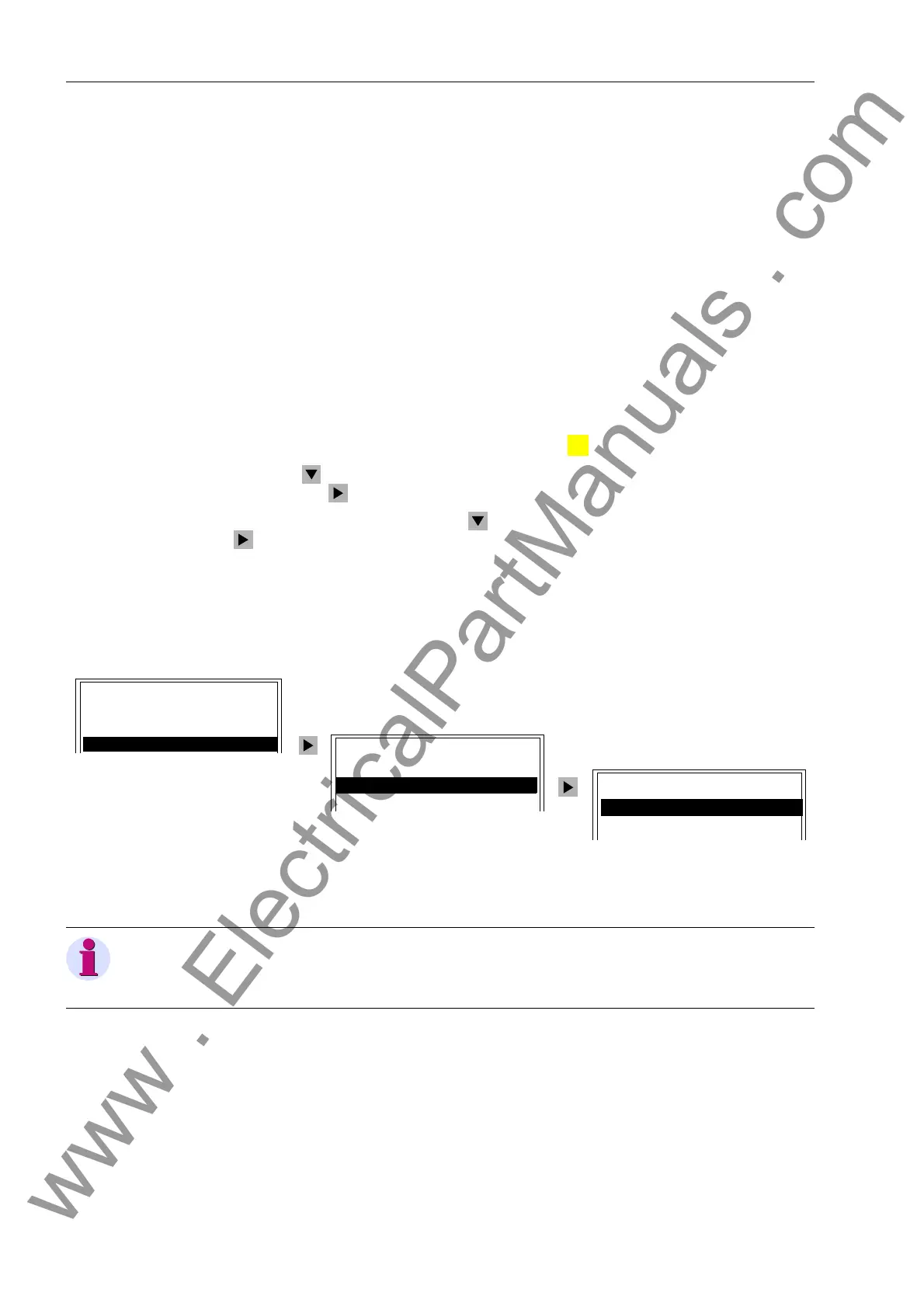
Select the item 7DJJLQJ with the key and switch to the next selection using the
key. The selection 7$**,1* appears. See Figure 7-53.
• The status of the tagging is displayed 7DJJLQJ → 'LVSOD\,
or changed using
• 7DJJLQJ → 6HW.
Figure 7-53 Tagging Equipment from the HMI
:
MENU
7$**,1*
'LVSOD\²!
6HW²!
&21752/
%UHDNHU6ZLWFK²!
7DJJLQJ²!
,QWHUORFN²!
0$,10(18
$QQXQFLDWLRQ²!
0HDVXUHPHQW²!
&RQWURO²!
Note:
The Manual Overwrite function is always done using the HMI on the SIPROTEC
®
4
devices.
www . ElectricalPartManuals . com

 Loading...


