Functions
6-112 7SJ62 Manual
C53000-G1140-C121-1
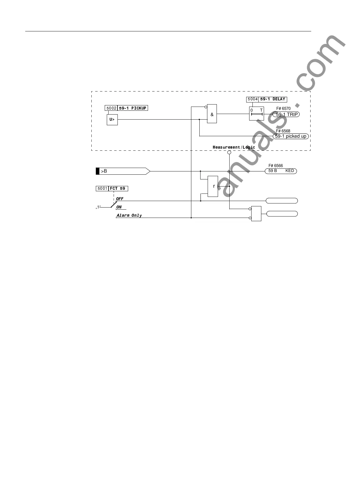
nal. The 59 element is a definite time element in that the time delay is not a function
of the voltage magnitude.
Figure 6-48 shows the logic diagram of the overvoltage protection element.
Figure 6-48 Logic Diagram of the Overvoltage Protection
6.11.1.3 Undervoltage Protection (27)
Application Undervoltage protection detects and reports abnormally low voltage conditions, some
of which could be related to system stability problems (voltage collapse, etc.). Under-
voltage protection is generally used to load shadding and loss of phase.
Function Undervoltage protection consists of two definite time elements designated 27-2 and
27-1. The pickup and delay settings of each element are individually adjustable. For
undervoltage protection, the positive sequence components of the phase-to-phase
voltages are evaluated. The 27 element is a definite time element in that the time delay
is not a function of the voltage magnitude.
With the 27-1 element, the ratio of drop out voltage to pickup voltage is settable as
well.
Figure 6-49 shows a typical voltage profile during a fault for source side connection of
the voltage transformers. Because full voltage is present after the circuit breaker is
opened, current supervision is unnecessary.
After the voltage has decreased below the pickup setting of the 27-1 element, the 27-
1 time delay is initiated, after which, the 27-1 element is used to block reclosing. As
long as the voltage remains below the drop out setting, reclosing is blocked. When the
voltage increases above the drop out level, the 27-1 element drops out and allows re-
closing of the circuit breaker.
3,&.83
'(/$<
T0
&
59-1 TRIP
59-1 picked up
21
2))
„1“
)&7
$ODUP2QO\
>BLOCK 59-1
59 OFF
&
59 ACTIVE
or
59 BLOCKED
0HDVXUHPHQW/RJLF
F# 6570
F# 6568
F# 6566
F# 6565
F# 6567
F# 6513
8!
www . ElectricalPartManuals . com

 Loading...


