Configuration
5-417SJ62 Manual
C53000-G1140-C121-1
5.5 Serial Ports
The device contains one or more serial ports — a PC-interface is integrated into the
front panel. Depending on the model ordered, a rear service port and a SCADA port
for connection of a substation control system are integrated. Certain standards are
necessary for communication via these interfaces, which contain protection device
identification, transfer protocol, and transfer speed.
Configuration of these interfaces is performed using the DIGSI
®
4 software program.
After opening the device, the user should click on 6HWWLQJ in the navigation window
and double-click in the data window on 6HULDO3RUWV. Next the user should select
the specific data in the resulting dialog box (Figure 5-43). The dialog box contains a
varying number of tabs (depending on the capabilities of the PC and the protection de-
vice) with setting options for the interfaces.
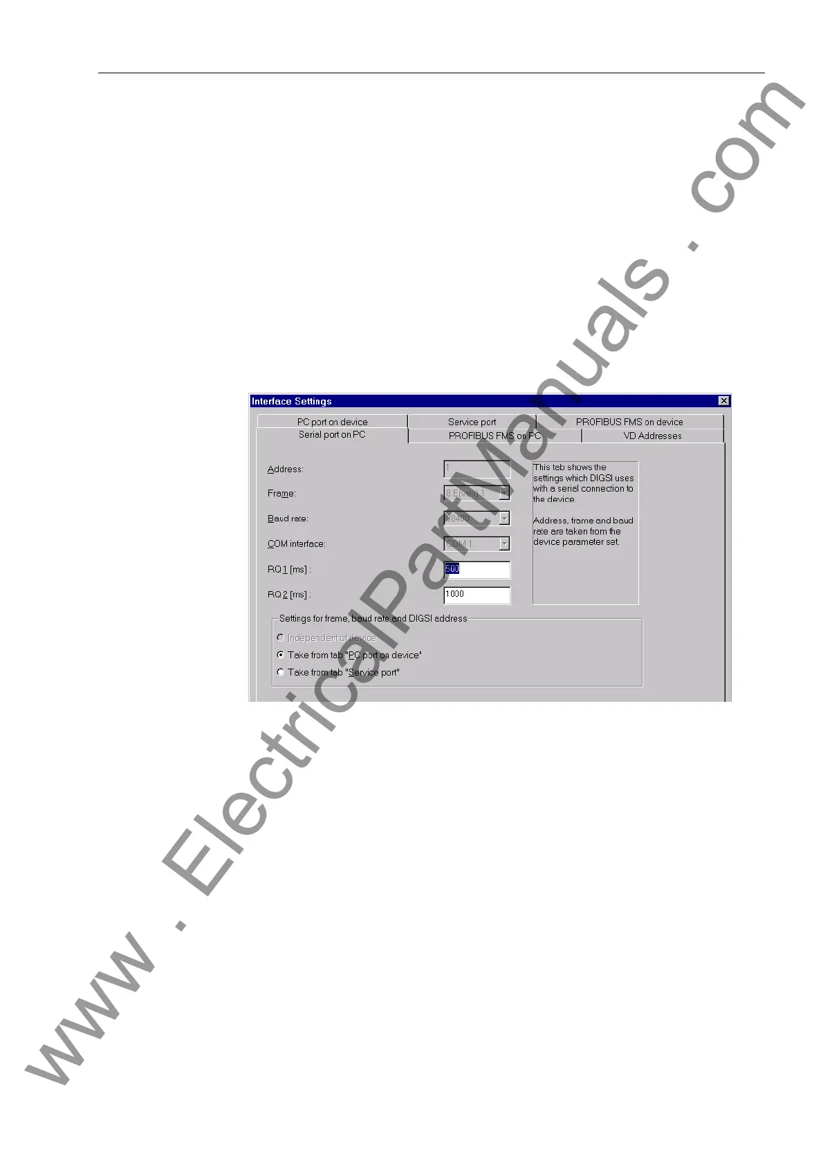
Figure 5-43 DIGSI
®
4, Settings of the PC Interface
Serial Port on PC In the first tab, the user should enter the communication port of the PC (&20&20
etc.) which is connected to the 7SJ62 relay. Manual entry of settings for data format
and baud rate can not be entered, since these values were taken from the “3&SRUW
RQGHYLFH” tab or the “6HUYLFHSRUW” tab (if present). In fact, many settings are
read from DIGSI
®
4 directly via the interface, and the corresponding setting fields are
made inaccessible (see Figure 5-43). On the other hand, for those settings that must
be entered by the user, the option ,QGHSHQGHQWRIGHYLFH should be selected.
The settings RQ 1 and RQ 2 are intended for Siemens use only. Please do not modify
these settings.
PC and Service
Ports of the Protec-
tive Device
Settings for link addresses and maximum message gap appear in the 3&SRUWRQ
GHYLFH and 6HUYLFHSRUW tab next to the settings for data format and transfer
speed (example Figure 5-44).
www . ElectricalPartManuals . com

 Loading...


