Operators Tools
7-37SJ62 Manual
C53000-G1140-C121-1
Binary Outputs Indications can be configured to binary outputs for external indication (e.g. annuncia-
tor, sequence-of-events recorder, RTU, etc ), and operate exactly like LEDs. See also
Chapter 5 for details.
Front Panel Display To retrieve messages using the front panel display on a device that is ready for oper-
ation:
First press the 0(18 key . The 0$,10(18 appears. The first menu item $QQXQ
FLDWLRQ) is marked.
All menus and message lists begin with a title. The number in the upper right hand cor-
ner of the display indicates the presently selected menu entry or message, and the
total number of menu entries or messages (see Figure 7-1, each first line).
Press the key to go to the $1181&,$7,21 sub-menu, as shown in Figure 7-1. In
this menu the messages can be reached by entering the associated selection number,
or by selecting the desired entry using the and keys and moving further with the
key. This procedure is described in more detail below.
Figure 7-1 Selection of Messages on the Operator Control Panel
PC–Interfaces A PC running the DIGSI
®
4 program can be connected to the serial port on the front
of the device or to the DIGSI interface port on the rear of the device to retrieve the mes-
sages. The rear DIGSI port connection can be RS232, RS485, or a multimode fiber
optic. The rear port is typically connected to a station computer or modem.
Details about the operation of DIGSI
®
4 are contained in the “DIGSI
®
4 Device Oper-
ation” handbook, order no. E50417-H1176-C097.
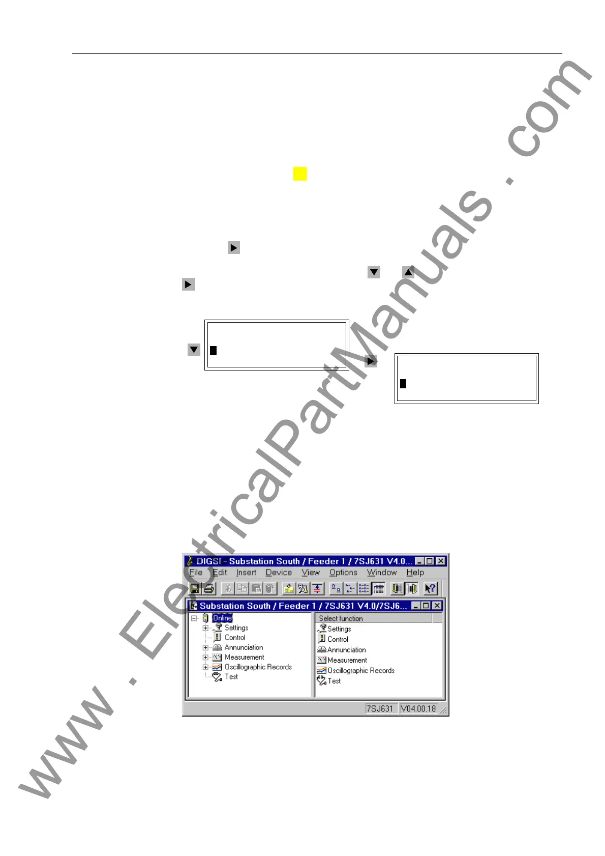
Figure 7-2 Function Selection Window in DIGSI
®
4
MENU
0$,10(18
!$QQXQFLDWLRQ²!
0HDVXUHPHQW²!
$1181&,$7,21
!(YHQW/RJ²!
7ULS/RJ²!
www . ElectricalPartManuals . com

 Loading...


