Operators Tools
7-177SJ62 Manual
C53000-G1140-C121-1
• I
1
, I
2
: positive and negative sequence components of the currents, primary in A and
kA, secondary in A and in % of the device nominal current.
• Va, Vb, Vc: phase-to-ground voltages, primary in kV, secondary in V and in % of
V
Nom
/√3, assuming that the phase-to-ground voltages are connected.
• Va-b, Vb-c, Vc-a: phase-to-phase voltages, primary in kV, secondary in V and in %
of V
Nom
.
• 3V
0
or Ve-n: displacement voltage, either directly measured or calculated as
3V
0
=(Va + Vb + Vc), primary in kV, secondary in V and in % of V
Nom
/√3, provided
that phase-to-ground voltages are connected.
• V
1
, V
2
: positive and negative sequence components of the voltages, primary in kV,
secondary in V and in % of V
Nom
/√3.
• S, P, Q: Apparent, Real, and Reactive power; primary in kVA or MVA or GVA, pri-
mary in kW or MW or GW, primary in kVAR or MVAR or GVAR, and in % of S
Nom
=√3
⋅V
Nom
⋅I
Nom
. The powers are positive if the real power and reactive power flow
into the protected equipment, assuming that this direction is set as “forwards” (Ad-
dress 0201, see Section 6.1).
• cos ϕ: power factor. The sign matches that of the real power.
• f: frequency in Hz.
•Θ/Θ
TRIP
: thermal value ratio, calculated temperature rise in % of the trip tempera-
ture rise or limit temperature rise.
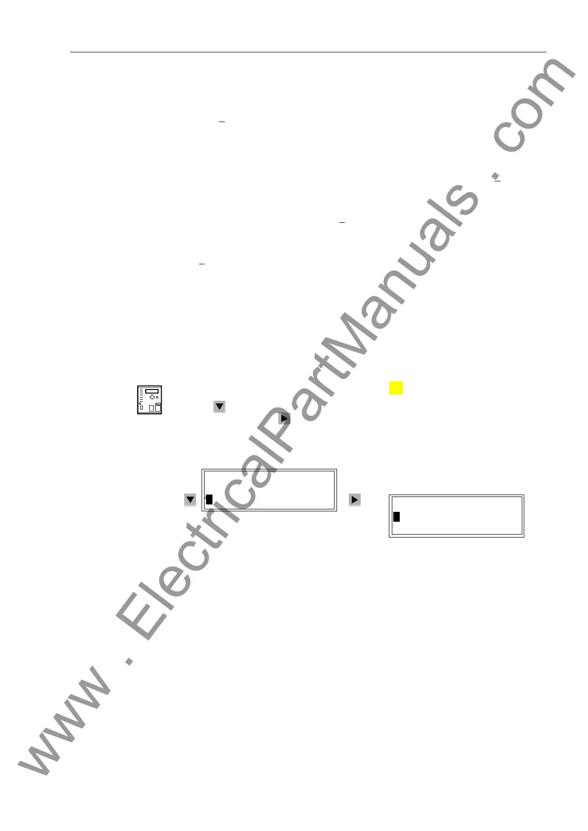
From the
Device Front
With a device ready for operation, first press the key. The 0$,10(18 appears.
Use the key to select the menu item 0HDVXUHPHQW, and switch to the list of mea-
sured values using the key. The 0($685(0(17 selection appears. See figure 7-
21.
.
Figure 7-21 Selection of Measured Values in the HMI — Example
The measured values are divided into the following groups:
1. 2SHUDWLRQSUL Operating measured values, primary.
The measured values are converted from secondary to pri-
mary according to the settings entered for the current and
voltage transformers, and the nominal device values.
2. ,1VSULPDU\ Ground fault values, primary.
The real portion, I
Nsw
, and reactive portion, I
Nsb
, of the (re-
sidual) ground connection current. The measured values
are converted from secondary to primary according to the
settings entered for the current and voltage transformers,
and the nominal device values.
MENU
Etc.
0$,10(18
$QQXQFLDWLRQ²!
!0HDVXUHPHQW²!
0($685(0(17
!2SHUDWLRQSUL
!2SHUDWLRQVHF
www . ElectricalPartManuals . com

 Loading...


