Operators Tools
7-36 7SJ62 Manual
C53000-G1140-C121-1
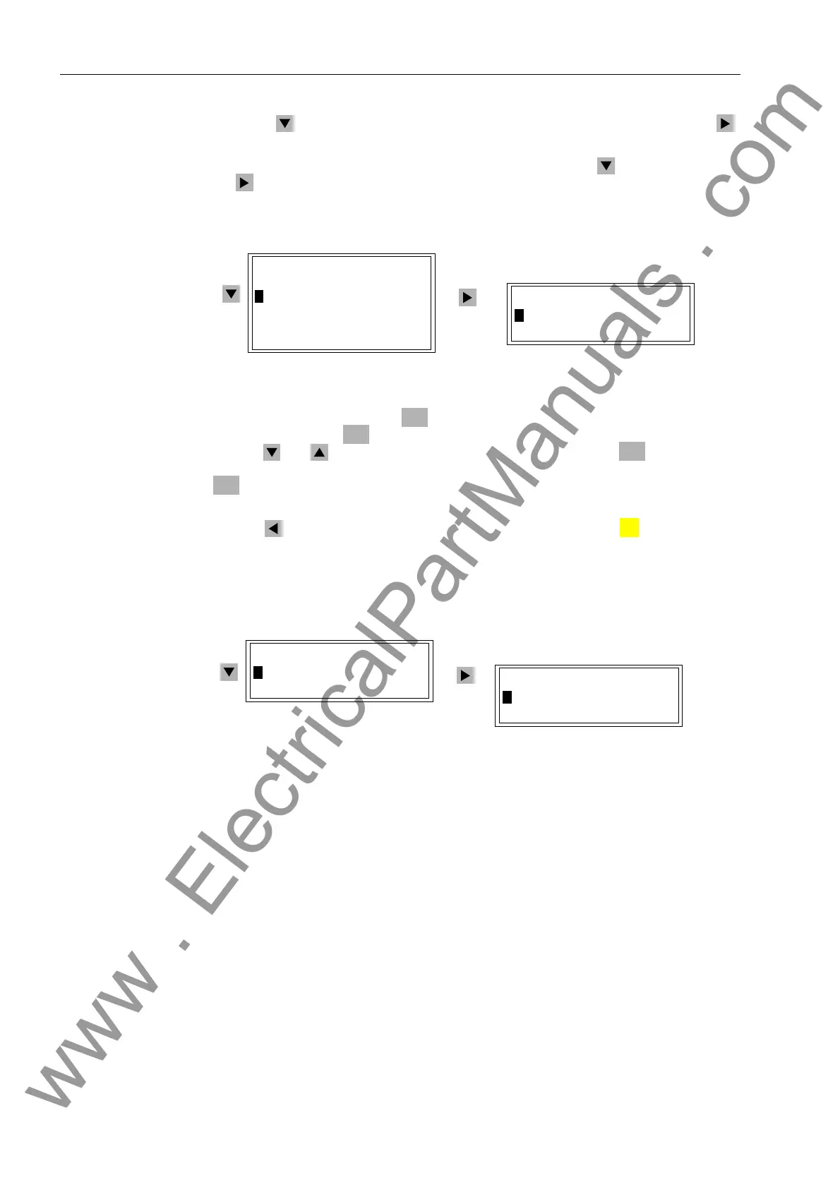
Using the key, highlight the menu item 7HVW'LDJQRVH, and then press the
key to enter sub-menu. 7(67',$*126( will appear at the top of the menu.
At this point, highlight the menu item 7HVW(QDEOH using the key, and then press
the key to enter sub-menu. 7(67(1$%/( will appear at the top of the menu. See
Figure 7-40.
Figure 7-40 Applying Test Mode from the Operator Control Panel
To start Test mode, press the key, enter the password for test and diagnostics,
and confirm with the key. A new window appears with the options 21 and 2)).
Use the and keys to select the desired mode, and press the key. The ques-
tion “$UH\RXVXUH"” is displayed. Highlight the desired response and press the
key. If the mode is changed, the device responds with the message “&RQWURO
([HFXWHG”.
Use the key to return to the 7(67',$*126( level; press the key to return to
the 0$,10(18.
The procedure for changing the Block Data Transmission mode is the same. See Fig-
ure 7-41 (simplified).
Figure 7-41 Applying a Block of Data Transmission from the Front Panel (simplified)
The settings for the test mode and the data transmission block are normally 2)). Def-
initions:
− 7HVWPRGH – With the 21 setting, the “test mode”-bit is transferred for messages
compatible with IEC 60 870–5–103.
− 'DWD6WRS – With the 21 setting, no messages or measured values are trans-
ferred (“transfer block”).
From PC with
DIGSI
®
4
Click on 'HYLFH in the menu bar to reach the commands %ORFN'DWD7UDQVPLV
VLRQ and 7HVW0RGH. See Figure 7-42.
7(67(1$%/(
!7HVWPRGH2))
7(67',$*126(
'HYLFH5HVHW²!
!7HVW(QDEOH²!
%ON'DWD7UDQV²!
+DUGZDUH7HVW²!
6HW5HVHW²!
6,(0(16,QWHUQ
ENTER
ENTER
ENTER
ENTER
MENU
7(67',$*126(
!%ON'DWD7UDQV²!
+DUGZDUH7HVW²!
%/.'$7$75$16
!'DWD6WRS2))
:
www . ElectricalPartManuals . com

 Loading...


