Installation and Commissioning
8-37SJ62 Manual
C53000-G1140-C121-1
q
Insert the device into the panel cutout and fasten with four screws. Refer to Figure
10-7 in Section 10.19 for dimensions.
q
Replace the four covers.
q
Connect the ground on the rear plate of the device to the protective ground of the
panel. Use at least one M4 screw for the device ground. The cross-sectional area
of the ground wire must be greater than or equal to the cross-sectional area of any
other control conductor connected to the device. Furthermore, the cross-sectional
area of the ground wire must be at least AWG 13.
q
Connect the plug terminals and/or the threaded terminals on the rear side of the de-
vice according to the elementary diagram for the panel.
When using spade lugs or directly connecting wires to threaded terminals, the
screws must be tightened so that the heads are even with the terminal block before
the lugs or wires are inserted.
A ring lug must be centered in the connection chamber so that the screw thread fits
in the hole of the lug.
Section 2.1 has pertinent information regarding wire size, lugs, bending radii (opti-
cal cables), etc.
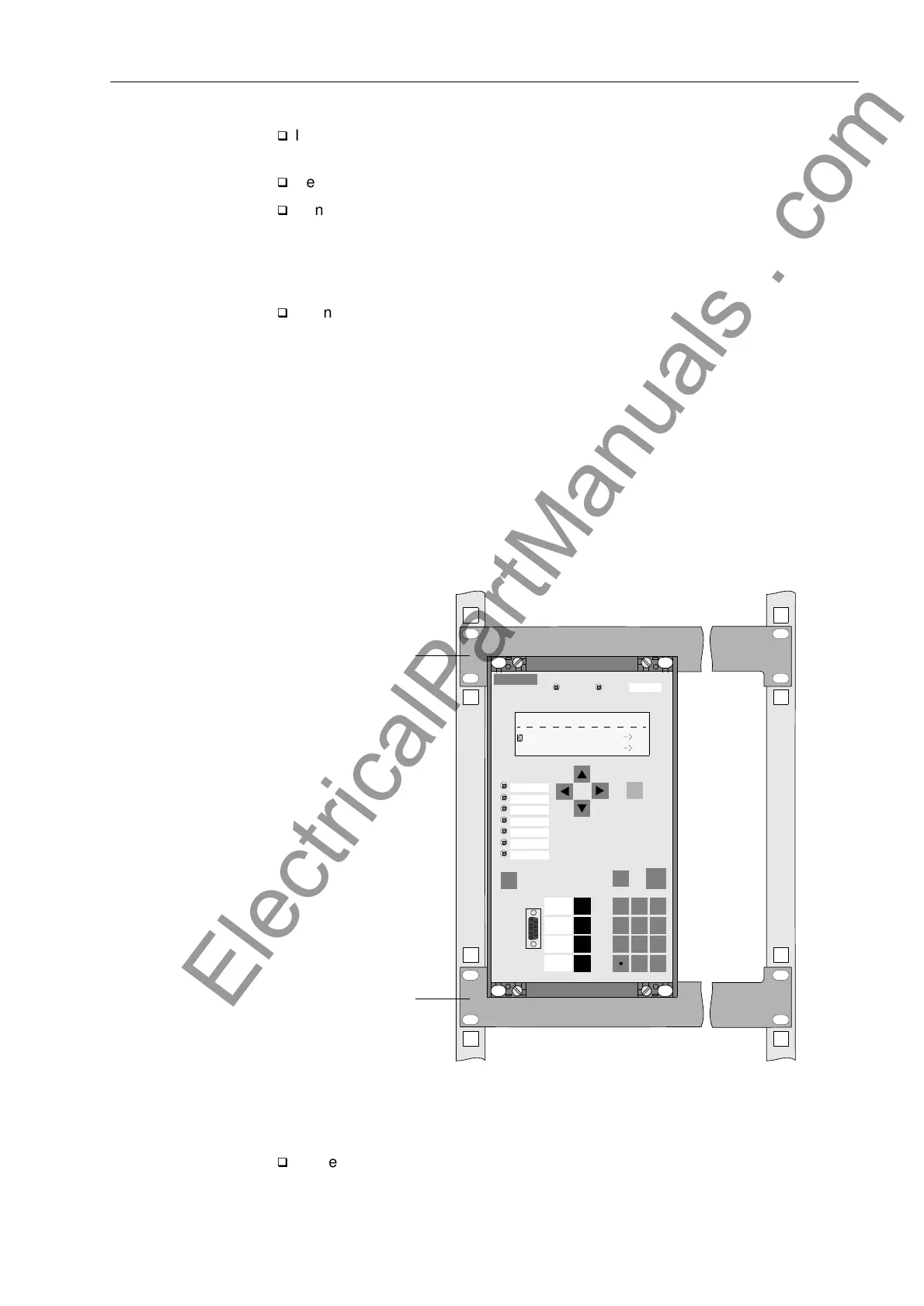
Rack Mounting Two mounting brackets are necessary to install the 7SJ62 in a rack. The order number
for the brackets is given in the Appendix, Sub-section A.1.3.
Figure 8-2 Installing a 7SJ62 in a Rack
q
Loosely screw the two mounting brackets in the rack with four screws.
SIEMENS
SIPROTEC
1 2
6
3
+/-0
54
7 8 9
TRIP
PICKUP A
PICKUP B
PICKUP GND
FAULT
PICKUP C
7SJ62
RUN ERROR
MENU
ESC
LED
ENTER
F4
F1
F2
F3
Events
Meter
MAIN MENU 01/05
Annunciation 1
Metering 2
Mounting
Mounting
Fault Data
Bracket
Bracket
www . ElectricalPartManuals . com

 Loading...


