5 – 22
5.4 Hilfsleiteranschlüsse
Klemmenbelegung
q Schaltpläne (Seite 8-1)
Querschnitte
1) Aderednhülsen sind zulässig
1 x bis 2,5 mm
2
Rohrform ohne Kunststoffhülse
1 x bis 1,5 mm
2
Rohrform mit Kunststoffhülse
2 x bis 1,5 mm
2
Rohrform mit Kunststoffhülse, Zwillings-Aderendhülse
2) 2 x bis 2,5 mm
2
Rohrform ohne Kunststoffhülse
2 x bis 1,5 mm
2
Rohrform mit Kunststoffhülse
Connection Type
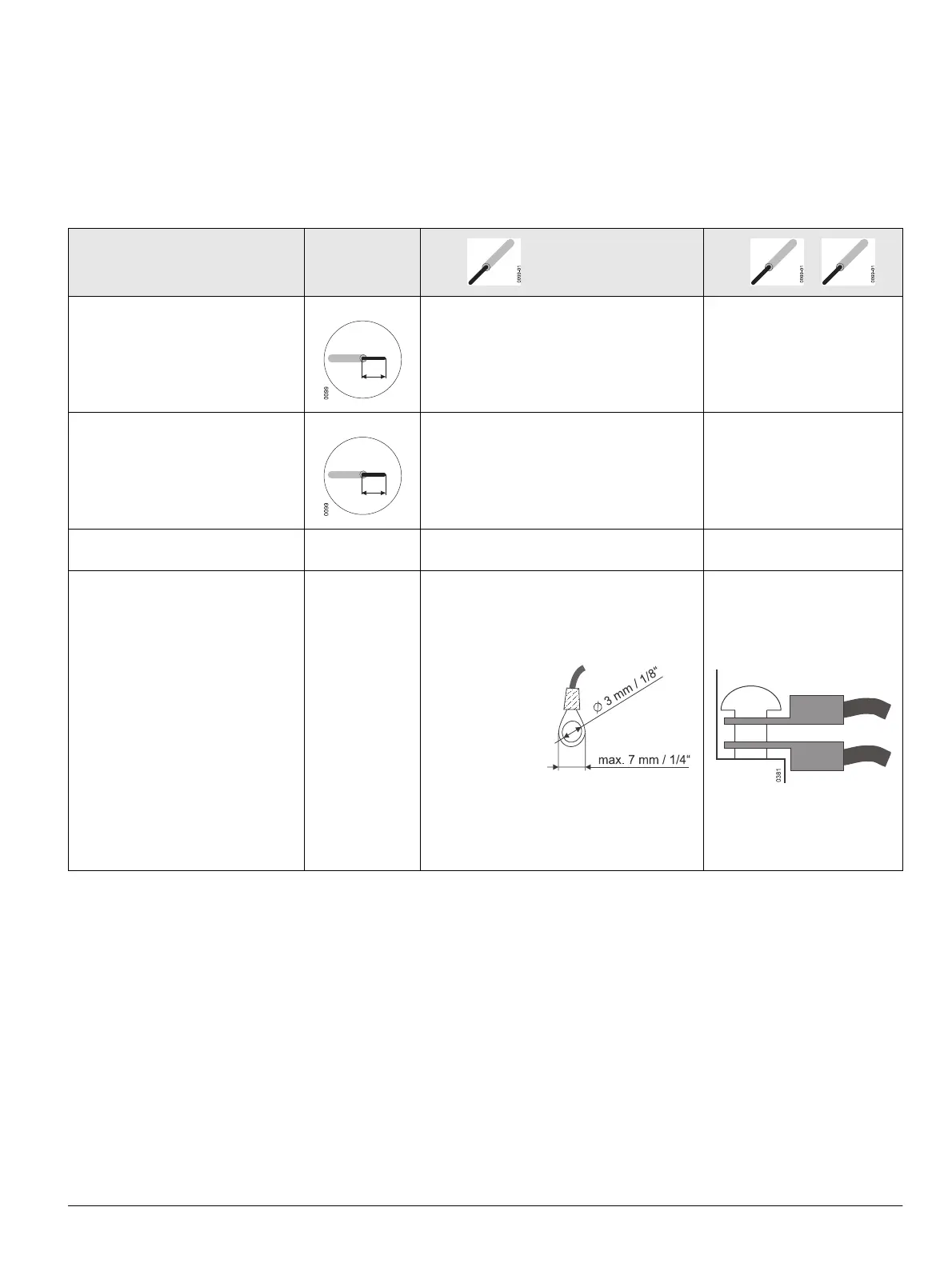
Anschluss-Typ
Strip Conductors
Leiter abisolieren
1 x 2 x
Screw-type terminal (SIGUT system)
Schraubklemmen (SIGUT-Technik)
20 -14 AWG1)
0.5 - 2.5 mm
2 1)
20 -14 AWG 1)
0.5 - 1.5 mm
2 1)
Screwless terminal system
Schraublose Anschlusstechnik
20 -14 AWG
1)
0.5 - 2.5 mm
2 1)
20 -14 AWG
2)
0.5 - 2.5 mm
2 2)
Pre-assembled wires
Vormontierte Leitungen
14 AWG
Length / Länge: 40” / 1 m
Ring terminal system
Ringösen-Schraubtechnik
14 - 16 AWG
7 mm 1/4“
7 mm 1/4“
Recommendation:
AMP, PIDG series
Catalog No. 50881
Empfehlung:
AMP, Reihe PIDG
Bestell-Nr. 50881
Recommendation:
Siemens part
Catalog No. WL10RL
10 AWG
Empfehlung:
Siemens part
Bestell-Nr. WL10RL
5.4 Secondary Wiring
Terminal assignment
q Circuit diagrams (page 8-1)
Cross sections
1) Use of wire end ferrules (crimp style) is possible
1 x up to14 AWG tube-type without insulating sleeve
1 x up to 16 AWG tube-type with insulating sleeve
2 x up to 16 AWG tube-type with insulating sleeve, twin wire end ferrule
2) 2 x up to 14 AWG tube-type without insulating sleeve
2 x up to 16 AWG tube-type with insulating sleeve

 Loading...


