A-2
4007ES Panel Programmer Manual (579-1167)
Required Operations
Introduction To comply with ULC standards, there are indicators and a key that must be programmed and
labeled, as outlined in this section. The LED indicators required are for Manual Evacuation,
Ground Fault, and AC Power On. User Button 1 is designated as the Manual Evacuation key.
Procedure For ease of programming, there is a check box in the Card Properties section of the Color
User Interface properties. Follow the steps outlined below to program the ULC required
items.
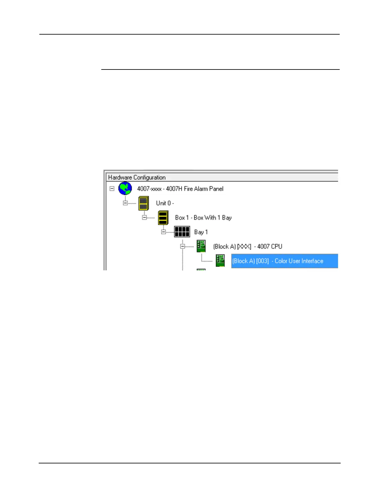
1. Click the Hardware tab and expand the Unit 0, Box 1, Bay 1, and Block A icons to display
the Color User Interface icon, see Figure A-1. Click the + signs to the left of the Unit 0, Box
1, Bay 1, and Block A icons to expand them.)
2. Right click the Color User Interface icon (highlighted in Figure A-1) and select Properties.
3. Click check box S527 Operation, as shown in Figure A- 2.
4. Click OK to close the dialog box.
Figure A-1. Expanded View of Hardware Configuration
Continued on next page