A-4
4007ES Panel Programmer Manual (579-1167)
Alarm Cutout Timer Feature
Introduction To comply with ULC standards when using the Alarm Cutout Timer feature, there must be a
yellow LED dedicated to indicate when the timer has expired.
Note: The LEDs adjacent to the LCD must be used for other ULC indication requirements, therefore the
inclusion of the Alarm Cutout Timer feature will require the additional LED Module (4007-9805).
Enabling Alarm
Cutout Timer
To enable the Alarm Cutout Timer, do the following:
1. Click the Panel tab.
2. Click the Systems Options subtab located at the bottom of the programmer.
3. Click the Alarm Cutout Timer checkbox. Specify the timer value on the Seconds box to the
right of the checkbox.
Programming the
LED
Step 1: Assigning a digital pseudo point for the LED.
1. Click the Point tab.
2. Scroll until the points with the Digital device type are visible. Select a point which has an
empty custom label field. (For purposes of demonstration, pseudo point P700 has been
selected.)
3. Right click on the point selected and select Properties.
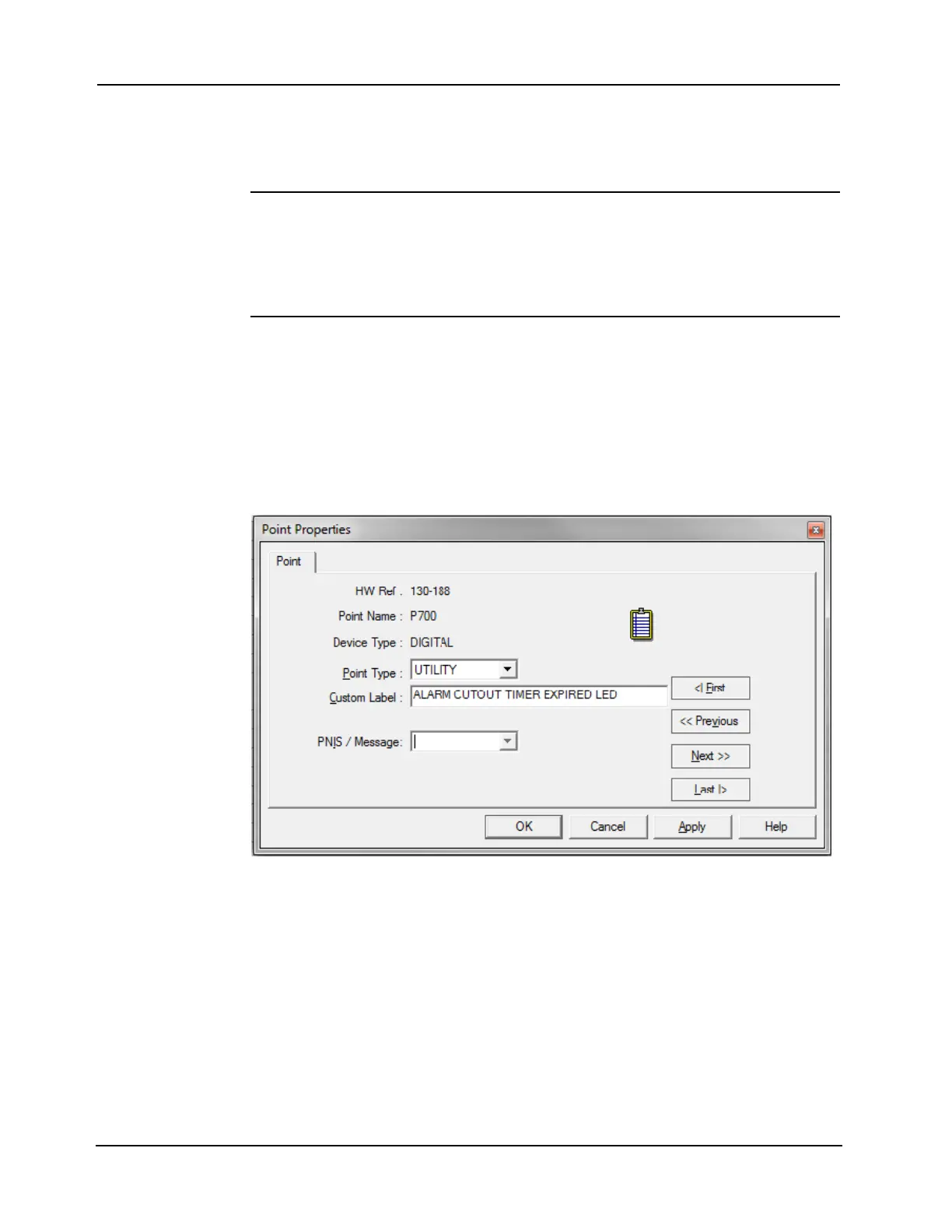
4. Enter the description in the custom label field, as shown in Figure A- 4.
5. Click OK.
Figure A- 4. Pseudo Point Properties
Step 2: Create Custom Control equations for pseudo point operation.
1. Review Chapter 8 of this manual for the process of creating Custom Control equations.
2. Create the equation shown below in Figure A-5, which turns the assigned pseudo point
ON when the Alarm Cutout Timer expires.
3. Create a second equation, shown in Figure A-6, which turns the assigned pseudo point
OFF when a subsequent alarm resounds the signaling devices and when the system is
reset.
Continued on next page