Section04ENGINE
Subsection 09 (ENGINE BLOCK)
1
R610motr136A
A
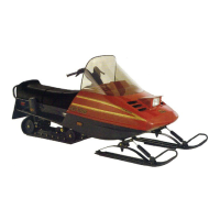
1. Measuring perpendicularly (90°)topistonpinaxis
A. 18 mm (.709 in)
The measured dimension should be as described
in the subsequent table. If not, replace piston.
PISTON MEASUREMENT mm (in)
NEW NOMINAL
99.951 to 99.969 mm
(3.935 to 3.936 in)
SERVICE LIMIT 99.80 mm (3.929 in)
Piston/Cylinder Clearance
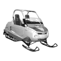
Adjust and lock a micrometer to the piston dimen-
sion.
F00B08A
1
1. Micrometer set to the piston dimension
With the micrometer set to the dimension, adjust
a cylinder bore gauge to the micrometer dimen-
sion and set the indicator to 0 (zero).
F00B09A
1
2
1. Use the micrometer to set the cylinder bore gauge
2. Dial bore gauge
F00B0AA
1
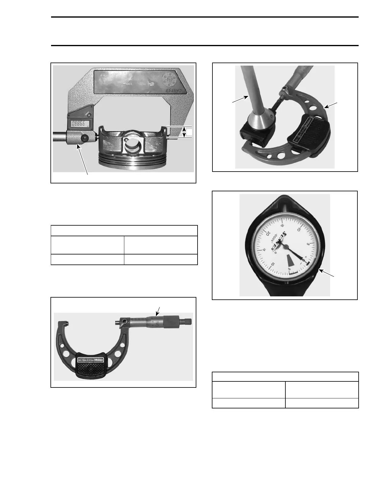
TYPICAL
1. Indicator set to 0 (zero)
Position the dial bore gauge 62 mm (2.44 in) above
cylinder base, measuring perpendicularly (90°)to
piston pin axis.
Read the measurement on the cylinder bore
gauge. The result is the exact piston/cylinder wall
clearance.
PISTON/CYLINDER CLEARANCE mm (in)
NEW NOMINAL
0.024 to 0.056 mm
(.0009 to .0022 in)
SERVICE LIMIT
0.090 mm (.004 in)
NOTE: Make sure used piston is not worn. See
PISTON MEASUREMENT above.
Te m pla te 161
 Loading...