Section04ENGINE
Subsection 09 (ENGINE BLOCK)
If clearance exceeds specified tolerance, rehone
cylinder sleeve and replace piston ass'y by an
oversize one.
NOTE: It is not necessary to have all pistons re-
placed with an oversize if they are not all out of
specification. Mixed standard size and oversize
piston are allowed.
NOTE: Make sure the cylinder bore gauge indica-
tor is set exactly at the same position as with the
micrometer, otherwise the reading will be false.
Piston Pin
Using synthetic abrasive woven, clean piston pin
from deposits.
Inspect piston pin for scoring, cracking or other
damages.
Measure piston pin. See the following illustration
for the proper measurement positions.
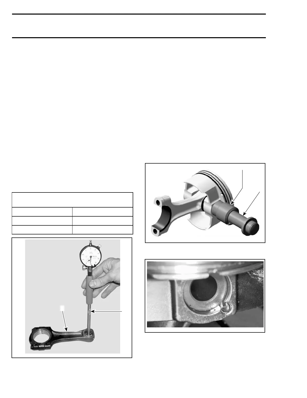
Piston Pin/Connecting Rod Bushing Clearance
Measure inside diameter of connecting rod.
CONNECTING ROD SMALL END
DIAMETER mm (in)
NEW MINIMUM 23.01 mm (.9059 in)
NEW MAXIMUM
23.02 mm (.9063 in)
SERVICE LIMIT 23.07 mm (.908 in)
1
R610motr73A
2
1. Bore gauge
2. Connecting rod
Replace connecting rod if diameter of connect-
ing rod small end is out of specifications. Refer
to CRANKSHAFT AND BALANCER SHAFT for re-
moval procedure of connecting rod.
Installation
For installation, reverse the removal procedure.
Pay attention to the following details.
Apply engine oil on the piston pin.
Insert piston pin into piston and connecting rod.
Use the piston circlip installer (P/N 529 035 765)
to assemble the piston circlip.
CAUTION: Secure piston pin with new piston
circlips
NOTE: Take care that the hook of the piston circlip
is positioned properly.
1
R1503motr28A
2
1. Sleeve with piston circlip inside
2. Assembly jig from piston clip installer
R610motr134B
CORRECT POSITION OF THE PISTON CIRCLIP
Using a piston ring compressor plier, such Snap-on
RC-980, slide piston into cylinder.
162 Te m plat e
 Loading...