MV-32/64 Multiviewer www.snellgroup.com Operation
Issue 1 Rev 11 Page 51 © 2014 Snell Limited
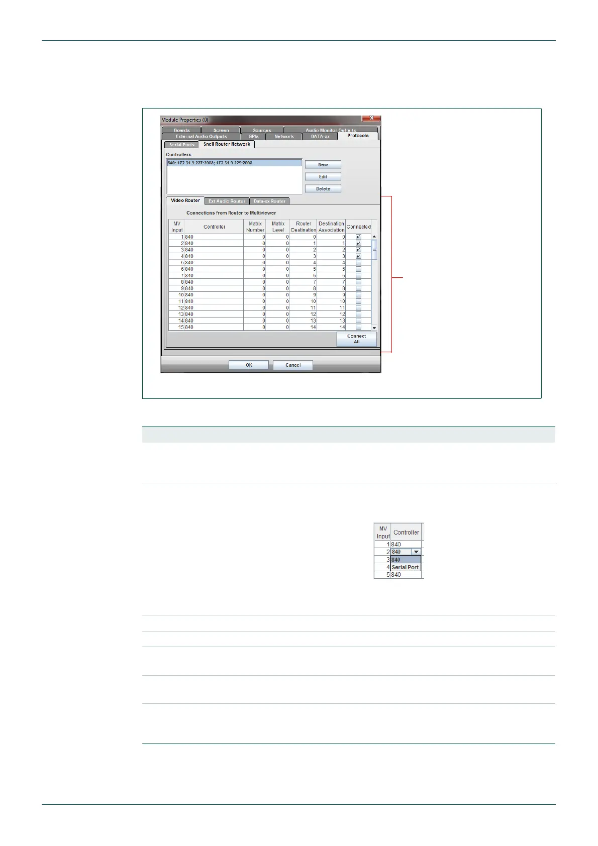
4.11.11.2 Connections from the Router Controller to the Multiviewer
There is a panel of sub tabs for each type of input source to the multiviewer, the tabs are
labelled: Video Router, Ext Audio Router and Data-xx Router.
The settings for each router are made in the same way as described in the following table:
Fig 39. Module Properties - Protocols - Snell Router Network Tab.
Column Description
MV Input
This column cannot be edited – it simply displays the input number of
the multiviewer input. This starts from 1 and goes up to the number of
inputs present on the multiviewer.
Controller
For each applicable multiviewer input, select the Snell controller that
controls the router that the source originates from by clicking on the
controller.
The options available from the drop down list are the Serial Port and
the controller name(s) that have been setup in the list box.
Matrix Number Matrix number that the router is in.
Matrix Level Level in the router or matrix that each input is contained in.
Router Destination
Physical output number of the matrix/router connected to the
multiviewer input.
Destination
Association
This will normally be the same as the Router Destination.
Connected
This must be ticked for each multiviewer input that is sourced from
the router. Any unticked inputs will not have their associated UMDs
set to follow the router’s source names.
Table 27. Router/Multiviewer Mapping Sub Tabs
Connections from the
Router Controller to the
Multiviewer
- see Table 27.