Devices and Chains - Front Panel Control
Your 16 pieces of outboard gear that are connected to the Insert Send and Returns connections can be routed to the desired
Insert Point from the front panel. Equally, any change you make in the Matrix Remote browser, will be mirrored on the Matrix
itself.
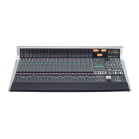
Please note that if the IN-LINE button is active,
the
DEVICES and CHAINS buttons will function
as
V-SOLO and V-MUTE commands instead. See
Chapter 5 for more information on these modes.
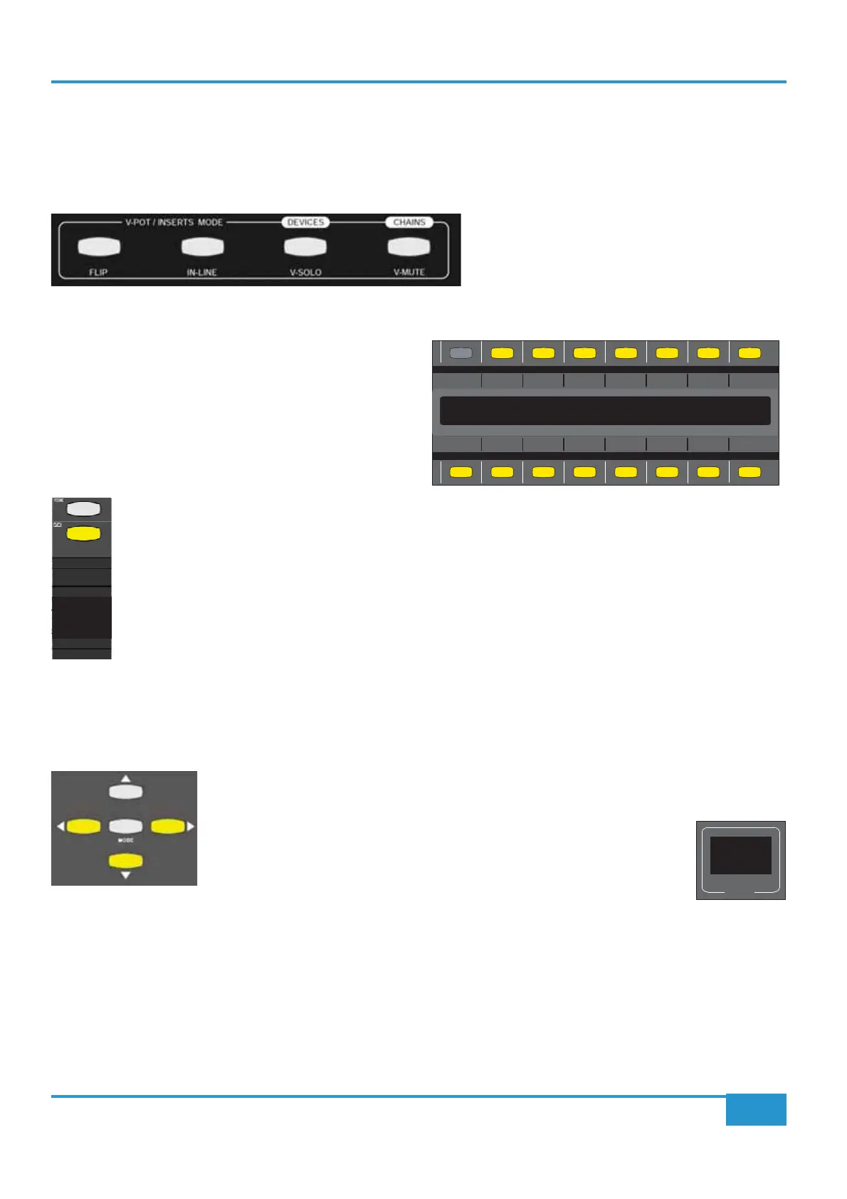
Devices
Pressing the DEVICES
on the right-hand side of Matrix to display the names of your
16 pieces of analogue outboard gear.
The two rows of eight buttons above and below the labels will
indicate if that particular
DEVICE is available.
If the button is lit (yellow) that device is available. If the button
is not lit, it is already inserted across a channel.
From this point, you can route outboard gear to each channel. Simply press the upper
SEL key on the channel you
want to insert something on and then press of the button corresponding to the device you want to insert.
That button will now unlight and the text will appear on the main LCD display, underneath the channel name. You
can follow the same procedure to insert devices on other channels.
Building Chains On The Fly
The Matrix will allow you to use up to 6 devices across a single channel’s insert point. With the DEVICES button still active,
go to a channel where you already have a single device insert across a channel. For example, we already have our “1176” device
inserted on the Bass channel but we want to put a “4K EQ” after it. To do this, we use the Navigation arrows.
Press the
DOWN arrow. Where the text displayed “1176”, you will now see a “*”. This indicates
the slot is available and all you need to do is press one of of the 16 devices corresponding to the
device you want to insert.
To further aid recognition of what you are doing, the two character
MODE
display will change to read “
- 2
that that channel.
The up and down arrows will allow you to move between slot numbers on a channel. You can only
MODE display will display
a small dot ‘
.’ to indicate when a particular channel has a device inserted on the next slot down.
The left and right arrows will allow you to move the upper
SEL
upper
SEL key directly).
Chapter 3 - Analogue Signal Flow
42
Matrix
2
Owner’s Manual
1176 LA-3A DIST 4KDYN MANL VHD 1176 4KDYN
9KDYN LA-2A THERM VULT DIST 9KEQ PURP LA-2A
Bass
1176
- 2
MODE