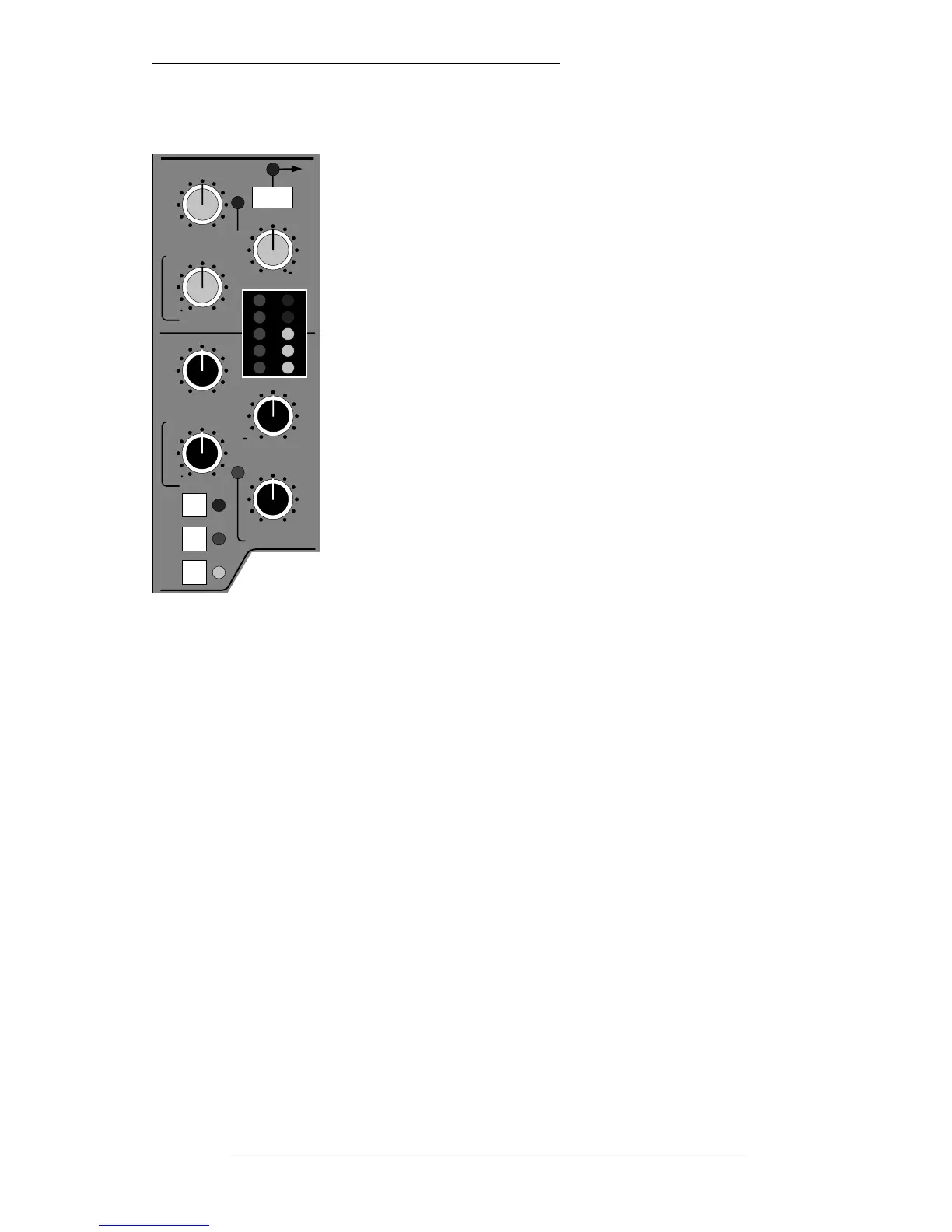
RELEASE – This determines the time constant (speed),
variable from 0.1 - 4 seconds, at which the Gate/Expander
reduces the signal level once it has passed below the threshold.
This control also incorporates a switch which, when pulled up,
provides a fast attack time (100µs per 40db). When down, a
controlled linear attack time of 1.5ms per 40dB is selected. The
attack time is the time taken for the Expander/Gate to
‘recover’ once the signal is above the threshold. When gating
signals with a steep rising edge, such as drums, a slow attack
may effectively mask the initial THWACK, so you should be
aware of this when selecting the appropriate attack time.
HOLD – Determines the time after the signal has decayed
below the threshold before the gate closes. Variable from 0 to 4
seconds. A pull switch on this control switches the section
from gate to expand operation.
The green LEDs indicate Expander/Gate activity (the amount
of gain reduction).
The LINK button at the top of the section links the side chain signal of that unit to the
side chain of the next Dynamics section along to the right. When two Dynamics
sections are linked, the control voltages of each section sum together, so that
whichever section has the most gain reduction will control the other section.
Note that it is not possible to link two gates so that the signal on one opens the other. If
you need to achieve this effect, take a keying signal from one section to trigger the
other. The easiest way to do this is by patching from the Insert Send of the ‘source’
channel into the Insert Return of the ‘destination’ channel, and selecting KEY (see
Page 3-8) on this channel.
Note that when the Dynamics section is not in circuit, its side chain input is also
bypassed.
The SL911 Input/Output Module
3-5
22.12.94
CH
IN
CH
OUT
MON
LINK
RATIO
20
14
10
6
3
DYNAMICS
PK
Pull
THRESHOLD
RELEASE
THRESHOLD
RANGE
RELEASE
HOLD
Pull for fast attack
Pull for fast attack
Pull for EXP
1
0
0
0
+10 20
1 4
0 40
30 +10
0
14
0 4
FILTER