MZC-88 Installation Instructions Page 19
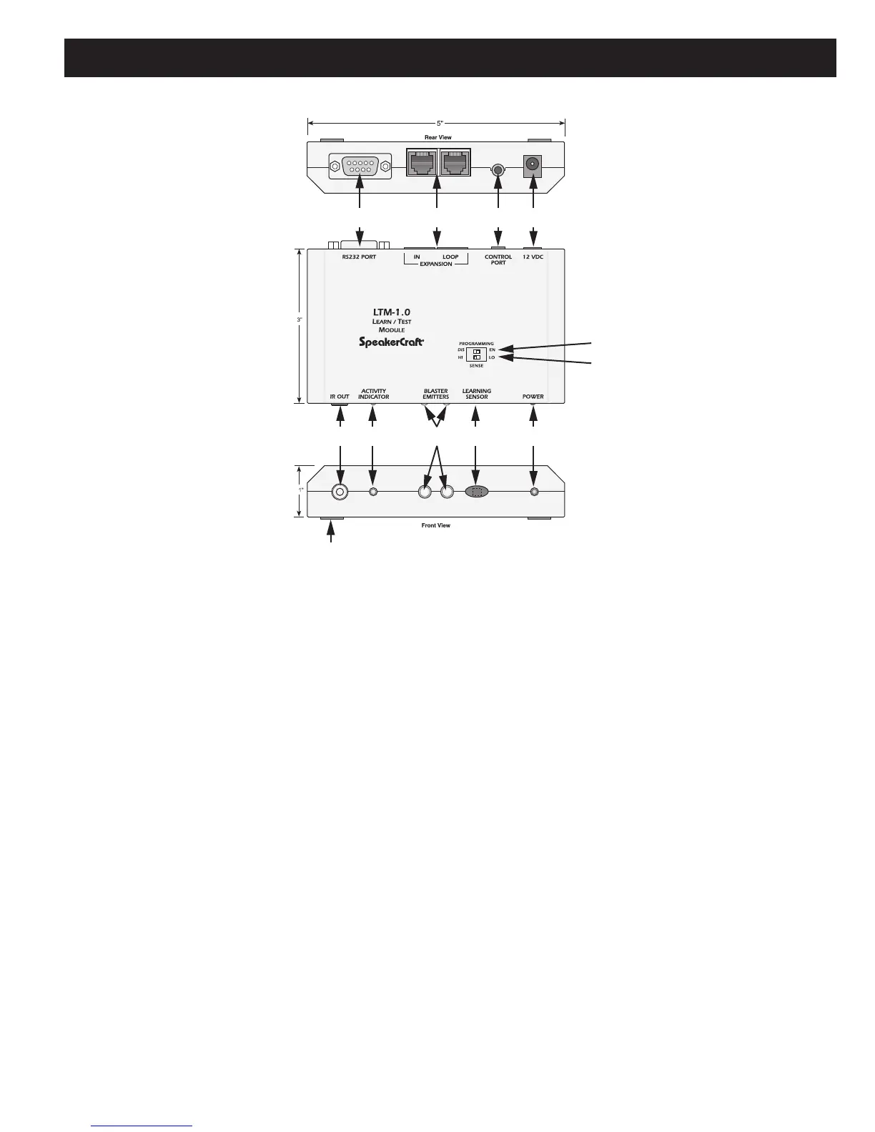
Figure 9
LTM-1.0 Learn/Test Module Features
1. RS232 PORT — One, DB9M jack outputs RS232 commands for testing control of RS232 controlled system compo-
nents.
2. EXPANSION PORTS — Two, RJ45 jacks provide connections for testing control of future RS485 controlled products.
3. CONTROL PORT — One, 3.5mm 4-circuit mini jack is a serial port that provides several control functions. All command
learning and testing functions are accomplished via this port, using EZ-Tools, in conjunction with the 3.5MM PLUG
TRANSFER CABLE. Firmware upgrades for the LTM-1.0 are also accomplished via this port.
NOTE: The 3.5mm Plug Transfer Cable would typically be connected to the DB9 COM Port on a PC. For computers
that do not have a DB9 COM Port, use the USB/SERIAL ADAPTER CABLE (Refer to Figure 8). When using a USB port,
connect the
USB/Serial Adapter and the 3.5mm Transfer Cable together. Connect one end to a USB port on the PC
running EZ-Tools and the other end of the assembled cable to the Control Port on the MZC-88.
4. +12V DC REGULATED — One, 2.1mm coaxial jack provides connection for a SpeakerCraft PS-1.0 12V DC 200mA
power supply (included).
POLARITY: PIN=+12V DC; SLEEVE=GND.
5. PROGRAMMING SWITCH — One, (upper) DIP switch DISables or ENables LTM-1.0 firmware upgrades. Leave this
switch in the DIS position at all times, unless performing a LTM-1.0 firmware upgrade. Such upgrades are accomplished
via EZ-Tools with the CONTROL PORT (item #3) connected to a PC running EZ-Tools. (This switch setting is for firmware
upgrades to the LTM-1.0 only.)
6. SENSE SWITCH — One, (lower) DIP switch sets the sensitivity of the internal IR Learning Sensor. This switch should
normally be set in the LO position. If the teaching remote has weak output, it should be switched to the HI position.

 Loading...