Page 20 MZC-88 Installation Instructions
7. POWER — Red LED indicates power supply is connected and the LTM-1.0 is active.
NOTE: If the Firmware Switch is set to ON the red power LED will not light.
8. LEARNING SENSOR — Internal IR sensor receives IR command data from external handheld remotes for learning IR
commands that are not available in the EZ-Tools IR command library. Point the “teaching” remote at this lens from a dis
-
tance of about 1 to 4 inches when “learning” IR commands.
9. BLASTER EMITTERS — These high power emitters output IR commands for testing and “teaching” purposes. When
testing commands, the Blaster Emitters should be pointing toward the device(s) to be controlled. The devices being
tested can be 30 feet or more away, with no obstructions. When “teaching” IR commands to a learning remote, point
the “learning” remote toward these emitters at a distance of about 1 to 4 inches.
NOTE: These Blaster Emitters are automatically disabled whenever an emitter or any 3.5mm mini plug is inserted into
the IR OUT jack (item #11).
10. ACTIVITY INDICATOR — Green LED, indicates IR learning mode activities. Also flashes during activation of internal
command data.
11. IR OUT — 3.5mm 2-circuit mini jack will drive any SpeakerCraft or other compatible emitters at medium power levels
for operational tests of IR commands. It will also drive one AT-1.0 Terminator block for connecting additional to test mul
-
tiple devices.
NOTE: The Blaster Emitters (item #9) are automatically disabled whenever a 3.5mm mini phone plug is inserted into
this jack.
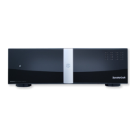
12. NON-SKID FOOT PADS

 Loading...