The STM32 Cortex-M0 processor PM0215
16/91 Doc ID 022979 Rev 1
Control register
The CONTROL register controls the stack used when the processor is in Thread mode. See
the register summary in Table 3 on page 12 for its attributes.
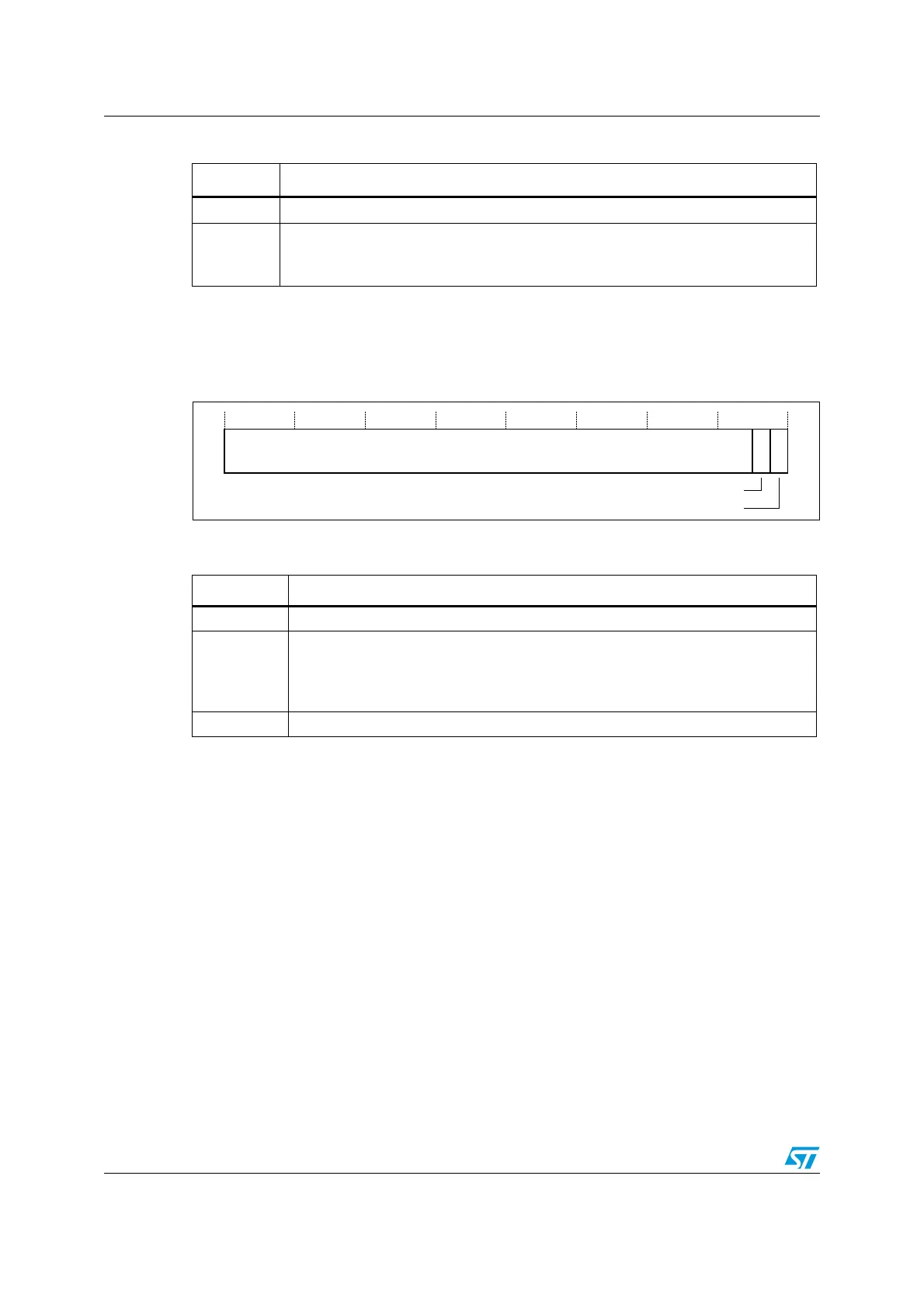
Figure 5. CONTROL register bit assignments
Handler mode always uses the MSP, so the processor ignores explicit writes to the active
stack pointer bit of the CONTROL register when in Handler mode. The exception entry and
return mechanisms update the CONTROL register.
In an OS environment, it is recommended that threads running in Thread mode use the
process stack and the kernel and exception handlers use the main stack. By default, Thread
mode uses the MSP. To switch the stack pointer used in Thread mode to the PSP, use the
MSR instruction to set the Active stack pointer bit to 1, see MSR on page 65. When
changing the stack pointer, software must use an ISB instruction immediately after the MSR
instruction. This ensures that instructions after the ISB execute using the new stack pointer.
See ISB on page 64
Table 8. PRIMASK register bit definitions
Bits Description
Bits 31:1 Reserved
Bit 0
PRIMASK:
0: No effect
1: Prevents the activation of all exceptions with configurable priority.
Table 9. CONTROL register bit definitions
Bits Function
Bits 31:2 Reserved
Bit 1 ASPSEL: Active stack pointer selection. Selects the current stack:
0: MSP is the current stack pointer
1: PSP is the current stack pointer.
In Handler mode this bit reads as zero and ignores writes.
Bit 0 Reserved
5HVHUYHG
$FWLYHVWDFNSRLQWHU
5HVHUYHG

 Loading...


