EasyManua.ls Logo

ST STM32F0 Series User Manual

ST STM32F0 Series
91 pages
To Next Page IconTo Next Page
To Previous Page IconTo Previous Page
Page #59 background imageLoading...
Page #59 background image
PM0215 The STM32 Cortex-M0 instruction set
Doc ID 022979 Rev 1 59/91
3.6 Branch and control instructions
Tabl e 21 shows the branch and control instructions:
3.6.1 B, BL, BX, and BLX
Branch instructions.
Syntax
B{cond} label
BL label
BX Rm
BLX Rm
where:
‘B’ is branch (immediate).
‘BL’ is branch with link (immediate).
‘BX’ is branch indirect (register).
‘BLX’ is branch indirect with link (register).
‘label is a PC-relative expression. See PC-relative expressions on page 39.
‘Rm’ is a register that indicates an address to branch to.
’Cond’ is an optional condition code, see Conditional execution on page 39.
Operation
All these instructions cause a branch to label, or to the address indicated in Rm. In addition:
The BL and BLX instructions write the address of the next instruction to LR (the link
register, R14).
The BX and BLX instructions cause a Hard fault exception if bit[0] of Rm is 0.
The BL and BLX instructions also set bit[0] of the LR to 1. This ensures that the value is
suitable for use by a subsequent POP {PC} or BX instruction to perform a successful
return branch.
Tabl e 22 shows the ranges for the various branch instructions.
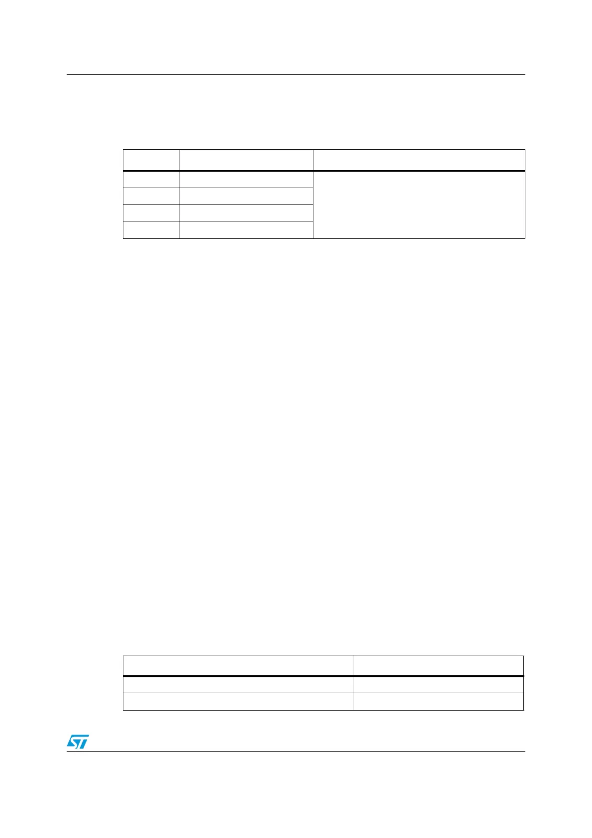
Table 21. Branch and control instructions
Mnemonic Brief description See
B{cc} Branch {conditionally}
B, BL, BX, and BLX on page 59
BL Branch with link
BLX Branch indirect with link
BX Branch indirect
Table 22. Branch ranges
Instruction Branch range
B label 2 KB to +2 KB
Bcond label 256 bytes to +254 bytes

Table of Contents

Other manuals for ST STM32F0 Series

Question and Answer IconNeed help?

Do you have a question about the ST STM32F0 Series and is the answer not in the manual?

ST STM32F0 Series Specifications

General IconGeneral
SeriesSTM32F0
CoreARM Cortex-M0
Operating FrequencyUp to 48 MHz
Flash Memory16 KB to 256 KB
SRAM4 KB to 32 KB
ADC Resolution12-bit
ADC ChannelsUp to 16
Operating Voltage2.0 V to 3.6 V
DAC Resolution12-bit (some series)
Communication InterfacesI2C, SPI, USART, USB, CAN
Operating Temperature-40°C to 85°C
Package OptionsLQFP, TSSOP, UFQFPN, WLCSP

Summary

Introduction to STM32F0xxx Programming

About this document

1.1 Typographical conventions

Defines typographical conventions used in the document.

1.2 List of abbreviations for registers

Lists abbreviations used for register descriptions.

1.3 About the STM32 Cortex-M0 processor and core peripherals

Overview of the Cortex-M0 processor and its core peripherals.

The STM32 Cortex-M0 processor

2.1 Programmers model

Describes the Cortex-M0 programmer's model, modes, and stacks.

2.2 Memory model

Details the processor memory map and memory access behavior.

2.3 Exception model

Explains the exception model, states, types, and priorities.

2.4 Fault handling

Covers fault handling mechanisms, including lockup states.

2.5 Power management

Describes sleep and deep sleep modes for power saving.

The STM32 Cortex-M0 instruction set

3.1 Instruction set summary

Summarizes the Thumb instruction set supported by the Cortex-M0.

3.4 Memory access instructions

Covers instructions for loading and storing data from/to memory.

3.5 General data processing instructions

Describes instructions for arithmetic, logical, and data manipulation operations.

3.6 Branch and control instructions

Details instructions for program flow control and branching.

Core peripherals

4.1 About the STM32 Cortex-M0 core peripherals

Introduces the core peripherals and their address map.

4.2 Nested vectored interrupt controller (NVIC)

Details the NVIC's support for interrupts and its registers.

4.3 System control block (SCB)

Describes the SCB for system implementation information and control.

4.4 SysTick timer (STK)

Explains the SysTick timer's functionality and registers.

Revision history

Related product manuals