The STM32 Cortex-M0 processor PM0215
26/91 Doc ID 022979 Rev 1
Exception entry
Exception entry occurs when there is a pending exception with sufficient priority and either:
● The processor is in Thread mode
● The new exception is of higher priority than the exception being handled, in which case
the new exception preempts the original exception.
When one exception preempts another, the exceptions are nested.
Sufficient priority means the exception has more priority than any limits set by the mask
registers, see Exception mask registers on page 15. An exception with less priority than this
is pending but is not handled by the processor.
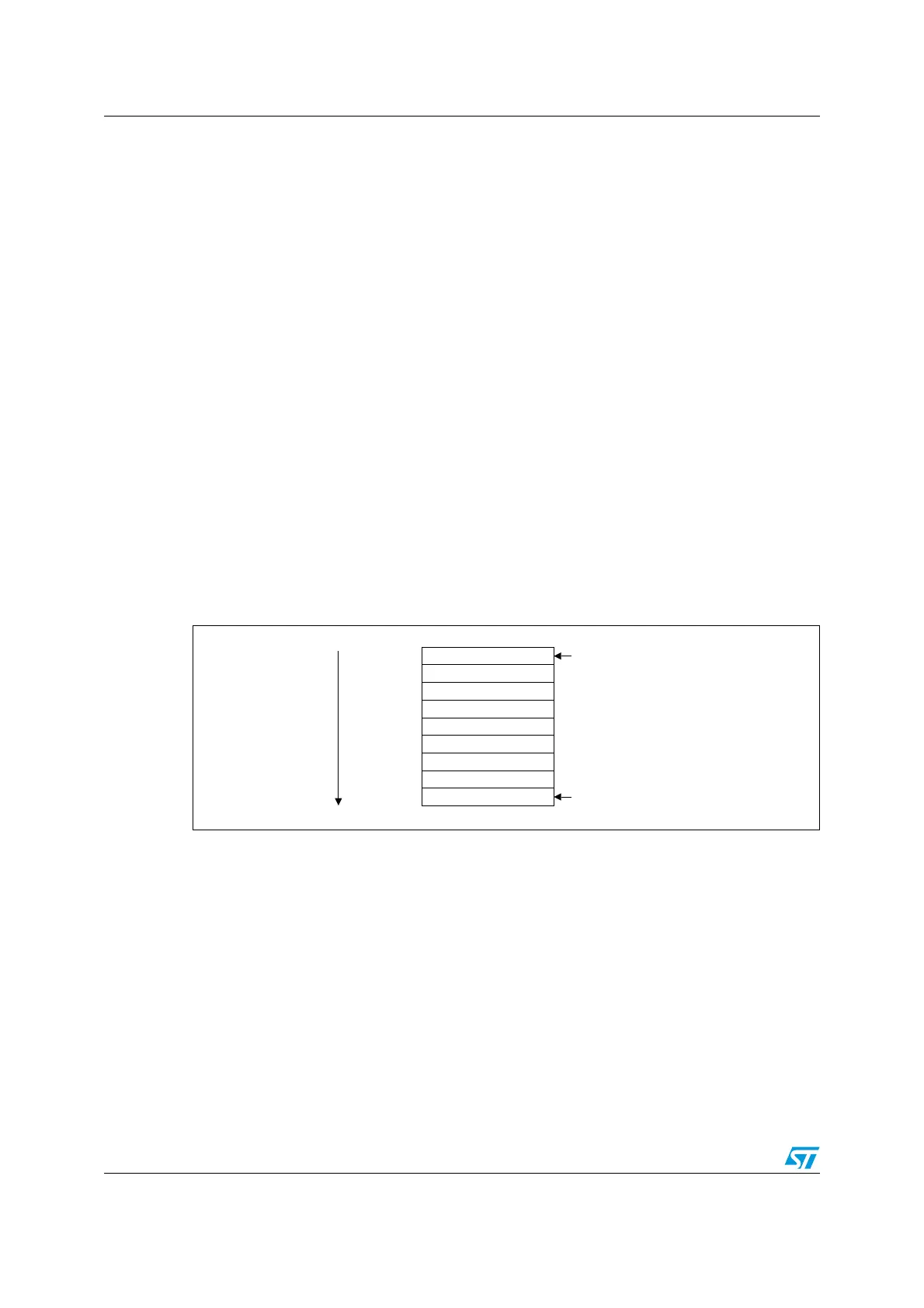
When the processor takes an exception, unless the exception is a tail-chained or a late-
arriving exception, the processor pushes information onto the current stack. This operation
is referred as stacking and the structure of eight data words is referred as stack frame. The
stack frame contains the following information:
Figure 9. Cortex-M0 stack frame layout
Immediately after stacking, the stack pointer indicates the lowest address in the stack frame.
The stack frame is aligned to a double-word address.
The stack frame includes the return address. This is the address of the next instruction in
the interrupted program. This value is restored to the PC at exception return so that the
interrupted program resumes.
The processor performs a vector fetch that reads the exception handler start address from
the vector table. When stacking is complete, the processor starts executing the exception
handler. At the same time, the processor writes an EXC_RETURN value to the LR. This
indicates which stack pointer corresponds to the stack frame and what operation mode the
was processor was in before the entry occurred.
If no higher priority exception occurs during exception entry, the processor starts executing
the exception handler and automatically changes the status of the corresponding pending
interrupt to active.
Late-arriving This mechanism speeds up preemption. If a higher priority exception occurs
during state saving for a previous exception, the processor switches to
handle the higher priority exception and initiates the vector fetch for that
exception. State saving is not affected by late arrival because the state saved
is the same for both exceptions. Therefore the state saving continues
uninterrupted. On return from the exception handler of the late-arriving
exception, the normal tail-chaining rules apply.
63SRLQWVKHUHEHIRUHLQWHUUXSW
[365
3&
/5
5
5
5
5
5
SUHYLRXV!
63SRLQWVKHUHDIWHULQWHUUXSW
63[&
63[
63[
63[
63[&
63[
63[
63[
'HFUHDVLQJ
PHPRU\
DGGUHVV
 Loading...


