PM0215 Core peripherals
Doc ID 022979 Rev 1 73/91
4.2.6 Interrupt priority register (IPR0-IPR7)
Address offset: 0x0300
Reset value: 0x0000 0000
The IPR registers provide an 8-bit priority field for each interrupt. These registers are only
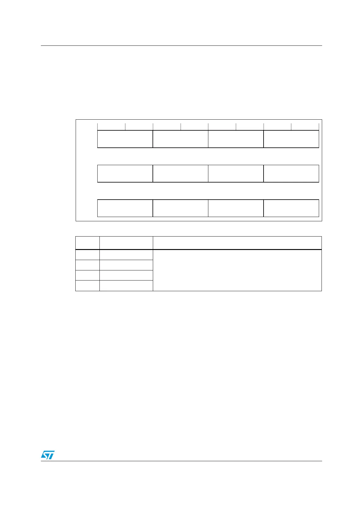
word-accessible. Each register holds four priority fields, as shown in Figure 14.
Figure 14. IPR register mapping
See Interrupt set-enable register (ISER) on page 71 Accessing the Cortex-M0 NVIC
registers using CMSIS on page 70 for more information about the interrupt priority array, that
provides the software view of the interrupt priorities.
Find the IPR number and byte offset for interrupt N as follows:
● The corresponding IPR number, M, is given by M = N DIV 4
● The byte offset of the required Priority field in this register is N MOD 4, where:
– byte offset 0 refers to register bits[7:0]
– byte offset 1 refers to register bits[15:8]
– byte offset 2 refers to register bits[23:16]
– byte offset 3 refers to register bits[31:24].
Table 27. IPR bit assignments
Bits Name Function
[31:24] Priority, byte offset 3
Each priority field holds a priority value, 0-192. The lower the value,
the greater the priority of the corresponding interrupt. The processor
implements only bits[7:6] of each field, bits[5:0] read as zero and
ignore writes. This means writing 255 to a priority register saves
value 192 to the register.
[23:16] Priority, byte offset 2
[15:8] Priority, byte offset 1
[7:0] Priority, byte offset 0
35,B
35,B 35,B 35,B
,35
35,BQ 35,BQ 35,BQ 35,BQ
,35Q
35,B 35,B 35,B 35,B
,35

 Loading...


