4-2
056404-443 Operator Manual Operating Instructions
4.3 Grounding
A patient grounding post/potential equalization terminal (male connector, DIN 42801) is provided. The mating
female connector for patient grounding is not furnished by STERIS.
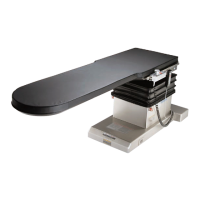
4.4 Positioning the Table
Position table at desired location, ensuring that the Vac electrical outlet is marked for the applicable power
system in the range of 100-240 Vac. See Section 4.7, Connecting Table to AC Power.
Note that the power cord is approximately 18 ft (5.5 m) long.
NOTE: The table is equipped with INTELLIPOWER
®
dual power system modes, enabling to operate from
connection to AC power or on its own battery power.
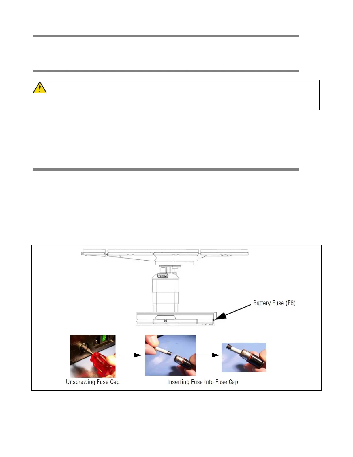
4.5 Installing Battery Fuse (F8)
If not installed, install 16A battery fuse (F8) (available in fuse set 342212555) into table base as follows:
1. Locate correct battery fuse.
2. At foot-end of table base, unscrew and remove black fuse cap.
3. Insert fuse in cap.
4. Insert fuse (with cap) into fuse holder assembly in table base.
5. Push in fuse and cap and turn a quarter turn to lock assembly into table base.
NOTE: If table is going to be stored for more than six months, remove fuse to limit battery discharge.
Figure 4-1. Installing or Replacing Fuses
WARNING – PERSONAL INJURY HAZARD: If an antistatic path is necessary, STERIS recommends
the use of antistatic pads (specifically developed for this table) in direct contact with the patient.
Table must also be positioned on antistatic floor or connected to equalization device
(equipotential connector).