6-13
Routine Maintenance Operator Manual 056404-443
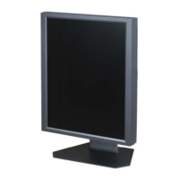
Figure 6-5. Seal Mating Areas Between Front and Rear Base Covers
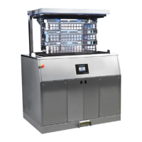
4. Apply RTV to bottom of each V-shaped cut-out around interface with column covers (see FIGURE 6-6).
Figure 6-6. Apply RTV to V-Shaped Cut-Outs
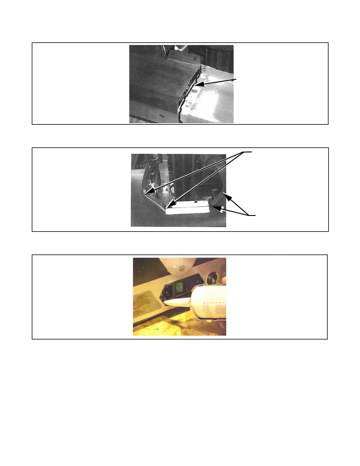
5. Seal area where power supply inlet is exposed through base (see FIGURE 6-7).
Figure 6-7. Seal Cover Around Power Inlet
6. Seal around entire perimeter between upper plastic column covers and column ensuring to fill entire gap as
shown in F
IGURE 6-8. Smooth out RTV as much as possible.