Z001019/0_6_July 2008 Page ENGINE - 79
01 ENGINE
SERVICE MANUAL MARINE ENGINES
01.08.03 Replace intercooler - element
Preparation: remove air filter, refer to 03.04.01
drain raw water circuit, refer to 05.00.07
remove intercooler, refer to 01.08.01
C
1
C
4
C
9
C
8
C
7
C
5
C
10
C
C
6
3
C
2
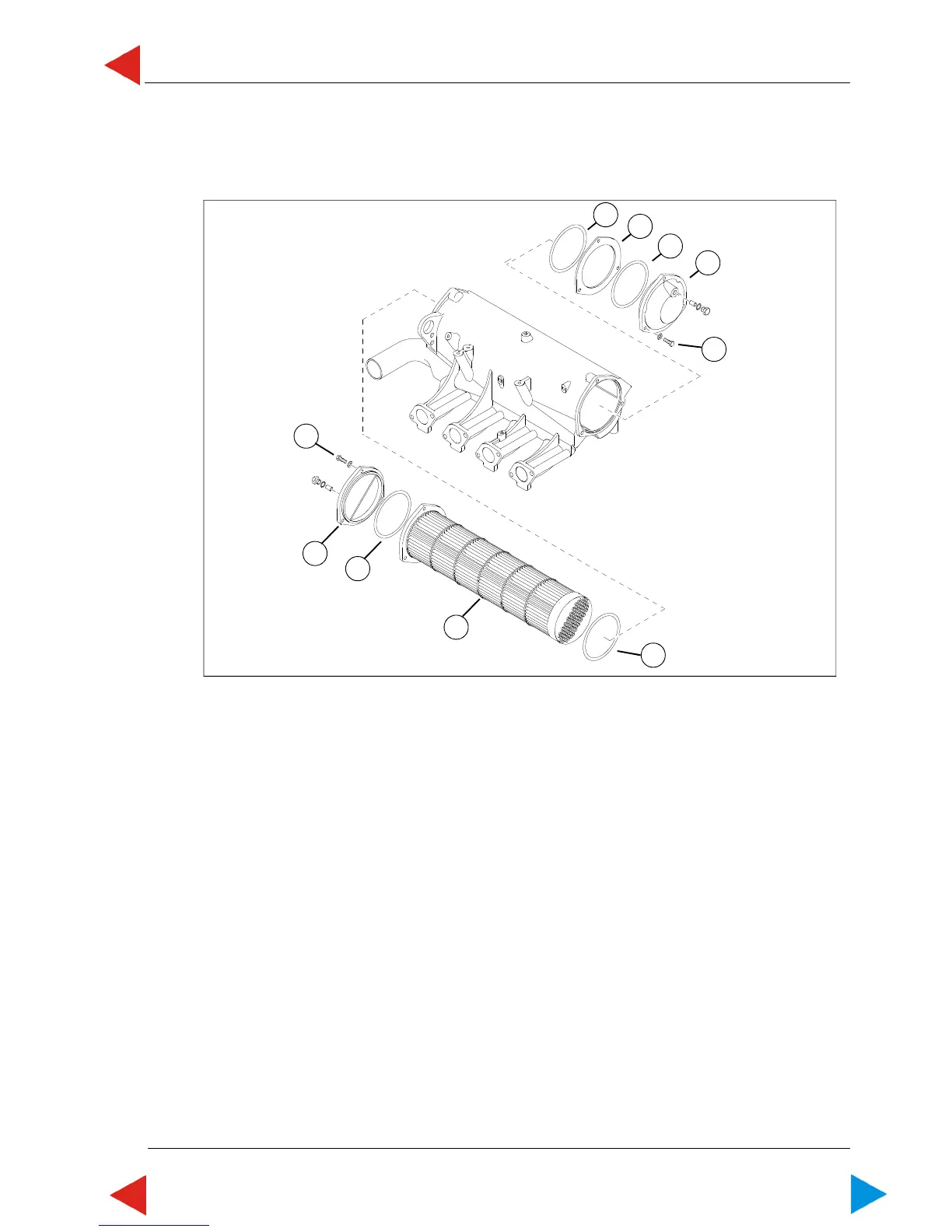
1 For engines with hydraulic systems, loosen upper screw; for all other engines, loosen 3 screws (ill.1/
pos.1) from intercooler cover in front and 3 screws (ill.1/pos.2) from intercooler cover at the back from
intercooler. Remove intercooler cover in front (ill.1/pos.4) and at the back (ill.1/pos.3).
2 Loosen the intercooler element by slightly knocking with a plastic hammer on the front end of the
element, and remove it. Dispose the O-ring of the element as well as the O-rings in the intercooler
covers.
3 Clean all sealing surfaces on intercooler, intercooler-element and intermediate flange.
4 Grease O-ring (ill.1/pos.5) with Molykote BR 2 PLUS and shift it up to the flange of the intercooler
element (ill.1/pos.10). Insert intercooler element into intercooler. Grease O-ring (ill.1/pos.6) with
Molykote BR 2 PLUS, insert it into intercooler cover (ill.1/pos.3), fix on intercooler and loosely mount
on intercooler with 3 screws (ill.1/pos.2).
5 Push O-ring greased with Molykote BR 2 PLUS (ill.1/pos.7), intermediate flange (ill.1/pos.8) and O-
ring greased with Molykote BR 2 PLUS (ill.1/pos.9) onto exposed end of intercooler element. Mount
intercooler cover in front (ill.1/pos.4) with upper screw (for all engines with hydraulic system) and all
other engines onto intercooler with 3 screws (ill.1/pos.1)
6 Tighten screws (ill.1/pos.2) with standard torque of 23 Nm +/-2.
NOTE: For engines with hydraulic system, tighten the screw (ill.1/pos.1) together with the two
screws for fixation of the hydraulic tank, with a torque of 23 Nm +/-2.
7 Remaining assembly is done in reverse order.
08.03 ill.1
ToC

 Loading...