Page COOLING SYSTEM - 26 Z001019/0_6_July 2008
SERVICE MANUAL MARINE ENGINES
05 COOLING SYSTEM
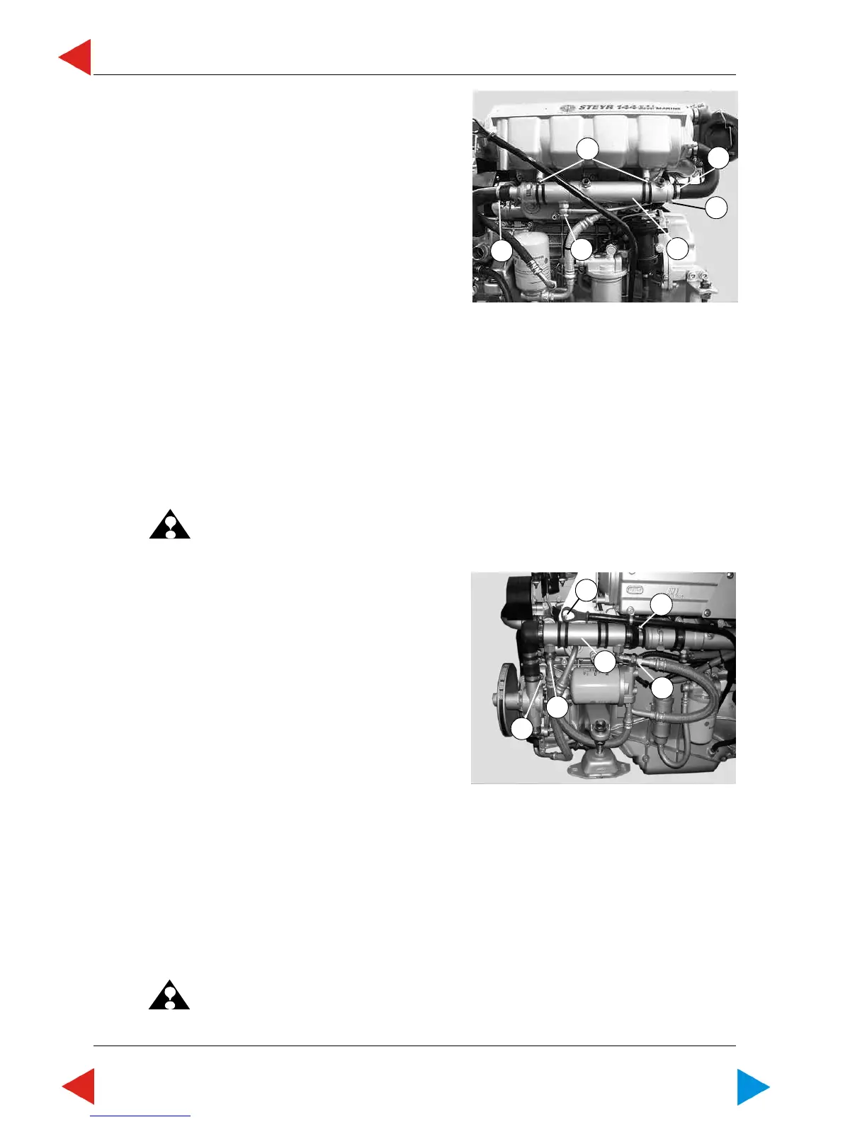
05.01.06 Exchange tandem cooler
Disassembly
Preparation: vent fuel system,
refer to 03.09/1
1. Remove drain plug (ill.1/pos.1) to drain the raw
water system.
2. Loosen hose clamp (ill.1/pos.2) of hose to raw water
pump, and remove hose.
3. Loosen hose clamp of hose bend (ill.1/pos.3) to
intercooler, and remove hose bend.
4 Loosen fuel return line (ill.1/pos.4) (SW19) mm and
hydraulic lines.
5. Unscrew two Allen head screws (SW6) (ill.1/pos.5)
of clamps, and remove tandem cooler (ill.1/pos.6).
Assembly
Assembly is done in reverse order.
ATTENTION: Use new sealing rings.
3
5
4
2
6
1
01.06 ill.1
05.01.07 Exchange additional oil cooler
(used only at type 246)
Disassembly
Preparation: loosen clamp oil dipstick (SW10)
1. Remove drain plug at tandem cooler to drain the raw
water system.
2. Loosen union nuts of oil hoses (ill.1/pos.1) (SW 21)
at the additional oil cooler.
3. Loosen hose clamp (ill.1/pos.2) of hose to raw water
pump.
4. Loosen hose clamp of hose (ill.1/pos.3) to tandem
cooler.
5. Unscrew two Allen head screws (SW6) (ill.1/pos.5)
of clamps, and remove additional cooler (ill.1/pos.6).
Assembly
Assembly is done in reverse order.
ATTENTION: Use new sealing rings for oil hoses.
Secure union nuts of oil hoses with
LOCTITE 243 and tighten with a
torque of 20 NM +/-2
01.07 ill.1
2
1
1
3
5
6
ToC

 Loading...