01 ENGINE
Z001019/0_6_July 2008 Page ENGINE - 7
SERVICE MANUAL MARINE ENGINES
01.00.03 Maintenance timing belt exchange
Preparation: put engine out of operation
disconnect battery
remove camshaft housing cover
Special tool: for vibration damper screws
No. 2300767/0
1 For 4 cyl. engines
Remove Poly-V-belt. See exchange of Poly-V-belt
(05.06)
2 For 6 cyl. engines
Remove all V-belts. See exchange of V-belts (05.07)
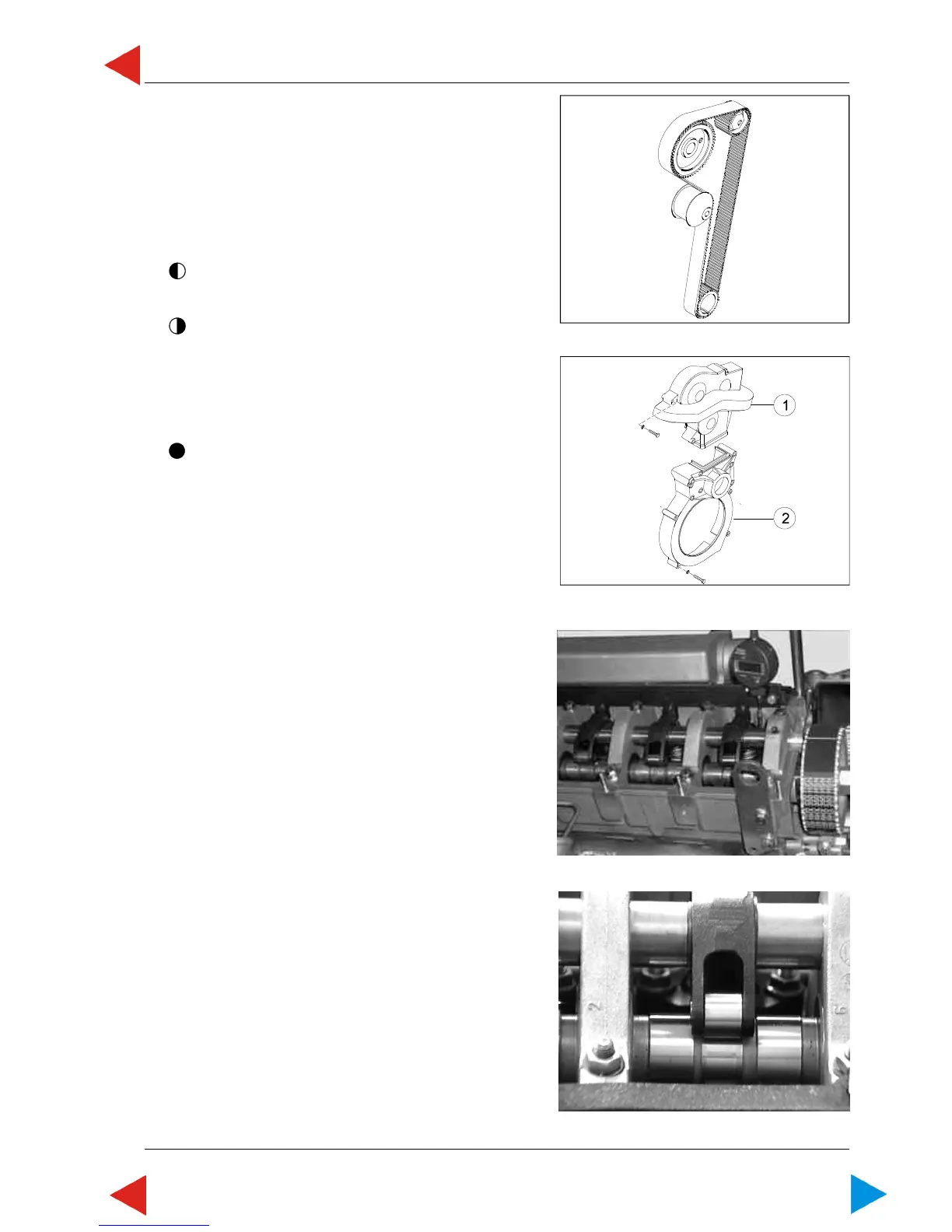
3 Unscrew 3 hexagon screws (SW10) of upper V-belt
covering (ill.2/pos.1) and remove V-belt covering.
4 Unscrew hexagon screws (SW 10) of lower timing
belt covering (ill.2/pos.2)) and remove timing belt
cover.
NOTE: See for arrows markings on used
timing belt; mark timing belt if
necessary.
Consider change intervals - see
chart "maintenance".
00.03 ill.1
00.03 ill. 3
00.03 ill. 2
00.03 ill. 4
Special tool: 2306031/4 dial gauge rail 4 cyl.
2306031/1 dial gauge rail 6 cyl. with
bossed seal surface
2306031/6 dial gauge rail 6 cyl. with
plane seal surface
2300899/0 dial gauge
2300641/1 probe pin
VR00515/0 V-belt tightener
2300711/0 open end wrench
VR00113/0 remover
2300551/2 locking pin
5 Mount dial gauge rail with brackets 2306031/. (see
list special tool) on studs at intake side of camshaft
housing.
6 Insert dial gauge 2300899/0 with probe pin
2300641/1 in dial gauge rail and put probe pin onto
unit injector-plunger guide cylinder 1.
7 Turn camshaft until the roller of rocker arm is located
on base circle of injection cam.
ToC

 Loading...