06 ELECTRICAL SYSTEM
Page ELECTRICAL SYSTEM - 38 Z001019/0_6_July 2008
SERVICE MANUAL MARINE ENGINES
06.03 ill.3
06.06.03 Reading Error Codes
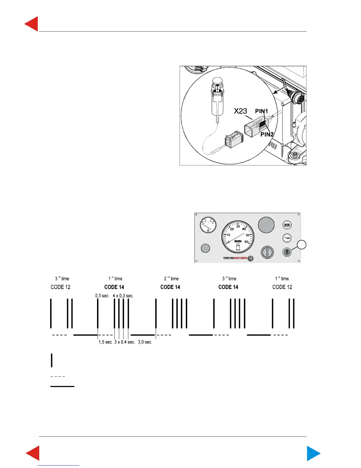
Entering and reading of stored faults via Check Engine Lamp and Diagnostic Outlet Plug ( X 23 ):
Needed device:
Tool No. VR00135/1
( normally closed push button switch )
connected to Diagnostic Outlet Plug X23.
In case this tool is not available:
Connect temporarily Pin - Pos. 1 with Pin - Pos. 2
of Diagnostic Plug X 23
( before ignition is turned on at key switch )
Code indication and indication sequence:
After entering the error code indication modus the Engine
Management System will display a blink code at the Check Engine Light on the dash panel.
The blinking sequence will always begin and end with control code indication # 12. Each ERROR CODE will be
repeated 3 times to reassure your correct reading – see below bar code illustration.
Example sequence check engine light (ill.2/pos.1):
Error code # 14
Stroke = Check Engine Light illuminated for 0,3 sec. (Light Off - period within blink sequence 0,4 sec.)
Dashed Line = interruption within code indication 1,5 sec.
Solid Line = interval interruption between error code 3,0 sec.
06.03 ill.1
1
06.03 ill.2
ToC

 Loading...