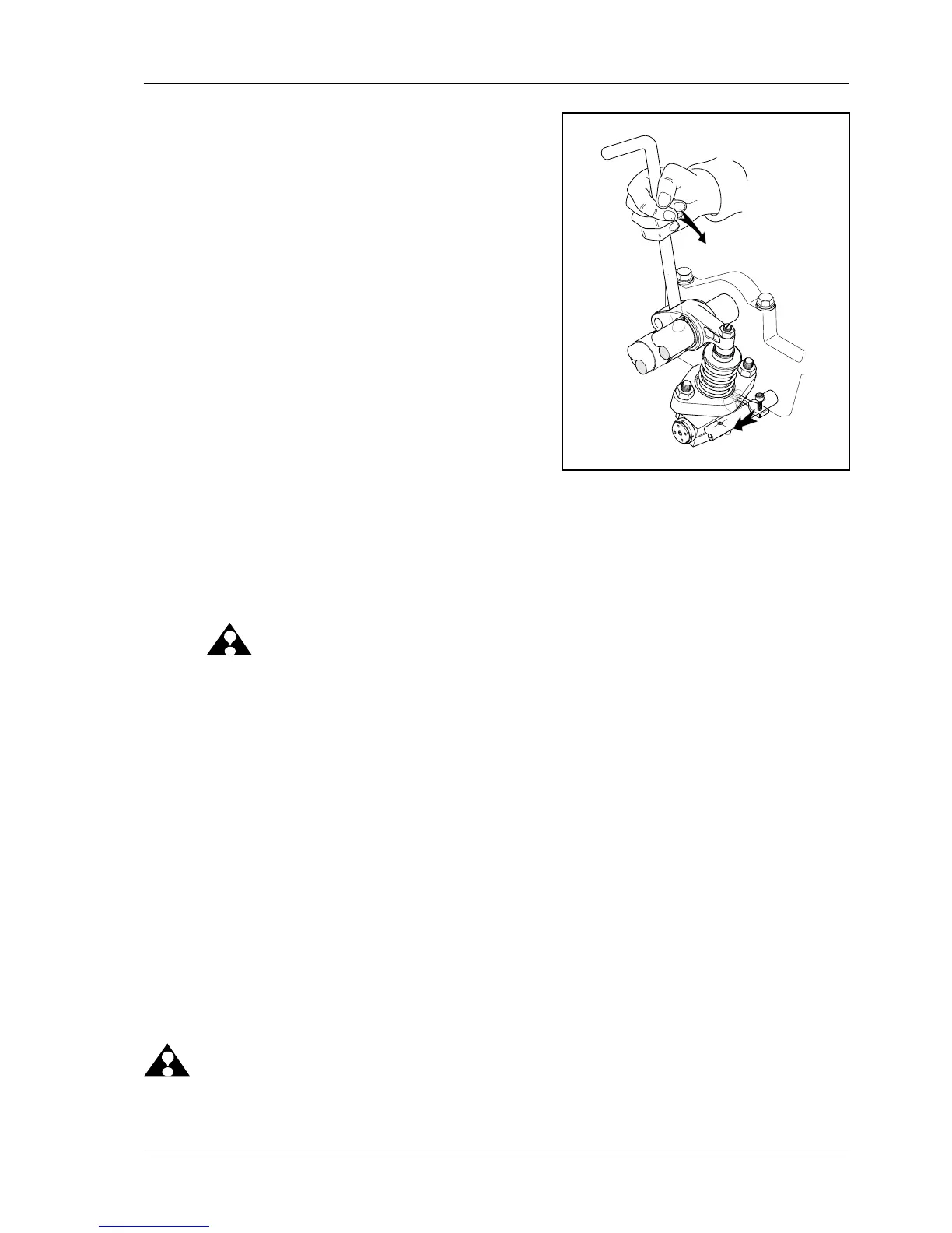
4 Put unit injector withdrawing lever No. VR00126/0
onto rocker arm of individual unit injectors (ill. 4) and
move upper end of lever in direction of air intake
manifold. As a result, unit injector is pressed down
and injection process is simulated.
NOTE: When moving the unit injectors, a
creaky noise is to be heard during
the injection process and/or a solide
resistance is to be felt due to pro-
duced injection pressure (pressure
point) .
If no difference is detectable in the individual unit
injectors, continue with item 5.
5 Adjust control rack by means of special tool No.
VR00148/0 to partial load (approx. 10-12 mm in di-
rection full delivery) (ill.3) and remain in this position.
6 Repeat item 4.
NOTE: Defective unit injectors which fail to produce a creaky noise in one or none of the two
checks and/or where no resistance (pressure point) can be felt are to be exchanged.
(Exchange unit injector, refer to 03.02.02).
7 Assembly is done in reverse order.
ATTENTION: Absolutely remove special tool
No. VR 00148/0.
Use new sealing ring.
Manual check of unit injector without tool No. VR 00148/0
Fuel System Check:
1. Investigate condition of return fuel. There should be neither air bubbles nor discoloration (gray) in the fuel.
2.Checkproperowquantity(i.e.engineatidle-owrateafterengineblock180to240l/hr;47to63gal.)
Injector Check:
To feel the injection activities, move the control rack (quantity delivery) in between its acceptable travel (5 to
14mm) while depressing the „plunger“ with the rocker arm. For safe and easier handling, use our special tool lever.
While moving the rocker arm (and/or the plunger up and down), try to get the control rack into idle delivery
position (approx. 4-5 mm). In this spot you will feel only a very slight/short pressure build up as the duration
of injection is very short (~ 5mm³/stroke).
Keepthispositiononthecontrolrack(freezethere)andthenmoveoverwithtoolVR00126/0tothenextunit
injector/rocker arm to repeat the plunge movement and feel the resistance during injection.
The test should give an equal pressure load/peak on each injector, while maintaining the same position on
the control rack.
If one injector fails to show any pressure or this pressure peak is found in a much higher position of the con-
trolrack,thisisanindicationforapossibledeciencyonthisinjector.
ATTENTION: Before removing this unit injector from the engine, check for proper adjustment of the linking
leverandforcorrectt/tightnessand/ortorqueoftheunitinjectormountingnuts.
14.01 ill.4

 Loading...