Z001019/0_6_July 2008 Page ELECTRICAL SYSTEM - 33
06 ELECTRICAL SYSTEM
SERVICE MANUAL MARINE ENGINES
B16
Z5
Z6
A
B
C
D
E
F
G
H
J
K
L
M
N
O
P
Q
R
S
T
V
W
X
U
R
Q
B
A
J1
STARTER
X23
1
2
3
6
5
4
1
2
3
6
5
4
S3
CONNECTOR "A5" (ELECTRONIC-CONTROL-UNIT)
J1 / U
J1 / V
60901-03
60900-03
60900-02
60901-02
5 CAN "H"
4 CAN "L"
X3/1 Invers
X3/2 Solas
60123-01
31000-11
61001-02
Batt + / 24V
D+ B+
B-
Batt - / 24 V
61001-01
F8
F8 - 5 A
2179345/0-02-070118_tedoc
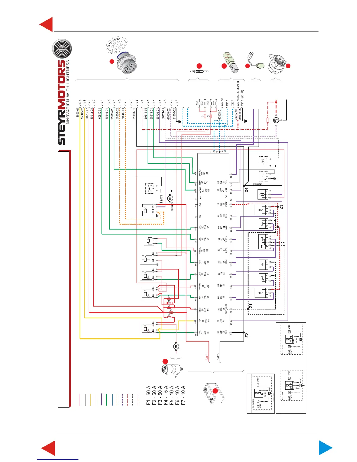
WIRING DIAGRAM / MARINE - 6 CYLINDER - 24V (OPTION)
www.steyr-motors.com
Batt +
Batt -
Ign 15
Supplied by Relais
Sens ECU
Control ECU
DIAG
Start
Charge D+
Sens 5V
Sens -
B+ 24V
G2
M2
Fuel
Pump
Fuel Pump
Relay
K24
Main
Relay
K27
Preheating
Control Relay
K26/1
Preheating
Load Relay
K26/2
Control
Solenoid
Y20
Start
Relay
K28
Trim-Sensor
(Option)
B22
60120-01
R10
60120-01
60808-01 ISO
60900-01 CAN-H
60901-01 CAN-L
60
123
-01
WS
G1
Sensor Oil
Pressure
Gauge
(Option)
B19
Gear
Switch
S2
RPM
B15
Map
B12
RPOS
B14
PED
B13
EXT
B17
EXT
LPS
ECT
AUX
ECT
B18
LPS
Wiring LPS / All engines before 2007
A
31100-10
15100-07
60117-01
EXCEPTIONS:
ONLY FOR TYP:
MO 164M40
MO 174V40
MO 246K41
MO 256H45
MO 256K43
MO 266K43
A
31100-08
15100-05
60110-01
Wiring MAP / All engines before 2007
31100-08
15100-05
60110-01
ALL ENGINE
TYPES WITH
FOLLOWING
EXCEPTIONS
05.03 ill.6
ToC

 Loading...