01 ENGINE
Z001019/0_6_July 2008 Page ENGINE - 11
SERVICE MANUAL MARINE ENGINES
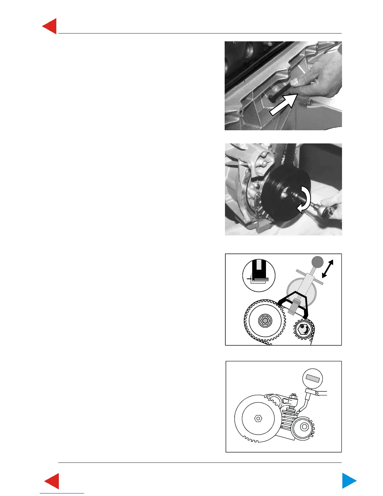
19 Remove locking pin from crank shaft.
20 Turn crankshaft 4 turns and stop at fourth turn with
a plunger guide stroke of unit injector of approx.
3.32 mm (dial gauge reading).
Then turn back crank shaft by a stroke measurement
of 0.5 mm on the dial gauge.
NOTE: During above mentioned operation
the timing belt should run into place
and a uniform tension shall result for
measuring of timing belt tension.
21 Put on tension gauge No. VR00515/0 between
camshaft sprocket and tensioner, as described,
and read measured value.
Timing belt tension should be 600 N +/- 30 N for a
new timing belt.
NOTE: If timing belt tension does not
correspond to specified tension, loosen
the tensioner and repeat adjustment
according to instructions under item
21 through 24.
In this case, a re-positioning of the
camshaft sprocket may be required.
22 Turn crankshaft further 2 turns, and at second turn
fix crankshaft with locking pin in TDC position
(cylinder 1; in TDC). See chapter 01.00.01.
With crank shaft in locked position, the plunger
guide stroke of the unit injector at first cylinder
should show the following value on the dial gauge:
Index value of engine timing
3.20 mm +/- 0,04 mm
(plunger guide stroke - unit injector)
00.03 ill.17
00.03 ill.18
00.03 ill.20

 Loading...