70 MS 362, MS 362 C
9.4.1 Machines with Heating
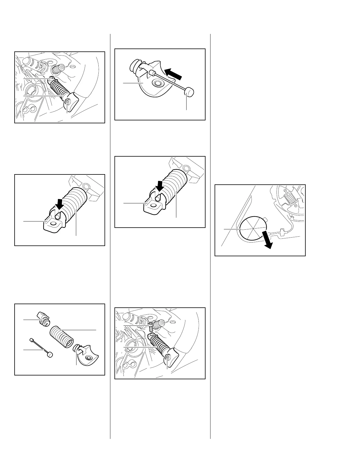
: Take out the screws (1) and (2).
: Remove the complete AV spring
(3).
: Unscrew the bearing plug (1) and
disconnect the retainer (arrow).
: Unscrew the spring (2) and pull
out the retainer (arrow).
– Inspect the bearing plug (1),
spring (2) and bracket (4) and
replace if necessary.
0001RA323 TG
1
2
3
0001RA219 TG
1
2
0001RA220 TG
1
4
2
3
Installing
: Push the retainer (1), small nipple
first, into the bracket (2).
: Screw the spring (2) onto the
bracket.
: Push the retainer (arrow) into the
bearing plug (1) and attach it.
: Screw the bearing plug (1) into
the spring (2) as far as stop.
: Position the complete AV spring
(1) on the handlebar.
0001RA221 TG
1
2
0001RA219 TG
1
2
0001RA223 TG
3
2
1
: Tighten down the screw (2) firmly.
: Coat the screw (3) with Loctite, fit
it and tighten it down firmly, b 15
– Reassemble all other parts in the
reverse sequence.
– Tightening torques, b 2.5
9.5 Annular and Stop Buffers
The stop buffers are located
between the tank housing and
crankcase. They are fitted at the
ignition and clutch sides.
Stop Buffer at Clutch Side
: Pry out the stop buffer (1).
– Check the stop buffer and
replace if necessary.
0001RA224 TG
1

 Loading...