28 MS 362, MS 362 C
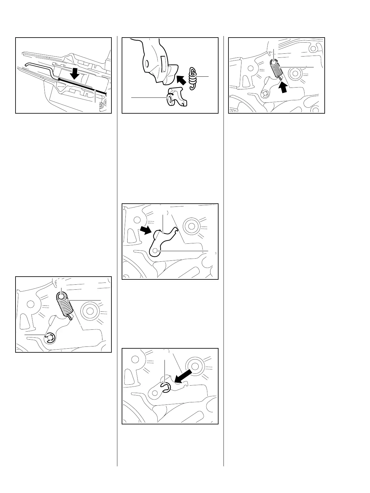
: Place the brake cable (1) in the
guide (arrow).
– Install the switch lever, b 10.3.1
– Check operation and adjust the
brake cable, b 5.4.1
– Reassemble all other parts in the
reverse sequence.
5.5 Cam Lever
The cam lever defines the locked
position of the hand guard.
– Remove the brake lever, b 5.3
: Disconnect the spring (1) from
the anchor pin (2).
: Remove the E-clip (3).
– Pull off the cam lever.
0001RA054 TG
1
1
0001RA454 TG
2
3
: Check the cam lever (1) and
spring (2) and replace if
necessary.
: Check the condition of the cam
contour (arrow) and replace the
hand guard if necessary.
Installing
– Position the cam lever (1) so that
its cam (arrow) faces the cam on
the hand guard.
: Push the cam lever (1) onto the
pivot pin (2).
: Fit the E-clip (1).
2
1
0001RA055 TG
219RA099 TG
1
2
1
0001RA056 TG
: Attach the spring (1) to the cam
lever so that the open side of the
spring hook (arrow) points toward
the housing.
If the groove in the spring's anchor
pin is worn, install a new pin, b 5.6
: Attach the spring (1) to the
anchor pin (2).
The cam lever is not yet under
tension – the spring may become
detached.
– Reassemble all other parts in the
reverse sequence.
– Tightening torques, b 2.5
– Lubricate the cam lever, b 15
1
2
0001RA455 TG

 Loading...