169 © STULZ GmbH – all rights reserved EN/01.2019/G22
ec tower technical manual
13
ENG
“OEM KUE” +030222130 - rel. 1.3 - 12.03.2015
4. CP, CPY, pCO
3
: HW CONFIGURATION AND RATED DATE
KUE models CP1- CP3 - CPY - pCO
3
models CP2 - CP4 models
KUE kg/h kW Vac Ph Inom
(A)
cable
[mm
2
]
line fuse
[A/type]
CP1 CP3 CPY
pCO
3
TAM
settings
Rate Turns TAM
for cylinder
with snap-on
connection
TAM
for cylinder
with screw
connection
CP2 CP4 Rate
4.b)
Turns TAM
for cylinder
with snap-on
connection
TAM
for cylinder
with screw
connection
SR 1,5 1,13 200 1 5,6 1,5 10A/gG R1C R1C R1C 100 TA EXT 1 a a R1C R1C 20 1 a a
208 1 5,4 1,5 10A/gG R1U R1U R1U 100 TA EXT 1 a a R1U R1U 20 1 a a
230 1 4,9 1,5 10A/gG R1D R1D R1D 100 TA EXT 2 d d R1D R1D 20 2 d d
3,0 2,25 200 1 11,3 2,5 16A/gG R3C R3C R3C 300 TA EXT 2 d d R3C R3C 60 2 d d
208 1 10,8 2,5 16A/gG R3U R3U R3U 300 TA EXT 2 d d R3U R3U 60 2 d d
230 1 9,8 2,5 16A/gG R3D R3D R3D 100 TA EXT 1 a a R3D R3D 20 1 a a
S1
1,5 1,13
200 1 5,6 1,5 10A/gG 01C 01C 01C 100 TA EXT 1 a a 01C 01C 20 1 a a
208 1 5,4 1,5 10A/gG 01U 01U 01U 100 TA EXT 1 a a 01U 01U 20 1 a a
230 1 4,9 1,5 10A/gG 01D 01D 01D 100 TA EXT 2 d d 01D 01D 20 2 d d
3,0 2,25 200 1 11,3 2,5 16A/gG 03C 03C 03C 300 TA EXT 2 d d 03C 03C 60 2 d d
208 1 10,8 2,5 16A/gG 03U 03U 03U 300 TA EXT 2 d d 03U 03U 60 2 d d
230 1 9,8 2,5 16A/gG 03D 03D 03D 100 TA EXT 1 a a
03D 03D 20 1 a a
T1
3,0
2,25 200 3 6,5 2,5 16A/gG - 03J 03J 100 TA EXT 1 a a - 03J 20 1 a a
208 3 6,2 2,5 16A/gG - 03W 03W 100 TA EXT 1 a a - 03W 20 1 a a
230 3 5,6 2,5 16A/gG - 03K 03K 100 TA EXT 1 a a - 03K 20 1 a a
400 3 3,2 1,5 10A/gG - 03L 03L 100 TA EXT 2 d d - 03L 20 2 d d
460 3 2,8 1,5 10A/gG - 03M 03M 100 TA EXT 2 d d - 03M 20 2 d d
S2 5,0
3,75 200 1 18,8 6,0 32A/gG - 05C 05C 500 TA EXT 2 d* d - 05C 40 1 e a
208 1 18,0 6,0 32A/gG - 05U 05U 500 TA EXT 2 d* d - 05U 40 1 e a
230 1 16,3 6,0 32A/gG - 05D 05D 500 TA EXT 2 d* d - 05D 40 1 e a
S3 8,7 6,53 208 1 31,4 16,0 50A/gG - 09U 09U 500 TA EXT 1 a a - 09U 60 1 a a
9,0 6,75 230 1 29,3 10,0 40A/gG - 09D 09D 500 TA EXT 1 a a - 09D 60 1 a a
T2
5,0
3,75 200 3 10,8 2,5 16A/gG - 05J 05J 300 TA EXT 2 d* d - 05J 60 2 d* d
208 3 10,4 2,5 16A/gG - 05W 05W 100 TA EXT 1 c a
- 05W 20 1 c a
230 3 9,4 2,5 16A/gG - 05K 05K 100 TA EXT 1 c a - 05K 20 1 c a
400 3 5,4 1,5 10A/gG - 05L 05L 100 TA EXT 1 a a - 05L 20 1 a a
460 3 4,7 1,5 10A/gG - 05M 05M 100 TA EXT 2 d d - 05M 20 2 d d
575 3 3,8 1,5 10A/gG - 05N 05N 100 TA EXT 2 d d - 05N 20 2 d d
8,0
6,00 200 3 17,3 6,0 32A/gG - 08J 08J 500 TA EXT 2 d* d - 08J 40 1 c a
208 3 16,7 6,0 32A/gG - 08W 08W 500 TA EXT 2 d* d - 08W 40 1 c a
230 3 15,1 6,0 32A/gG - 08K 08K 300 TA EXT 2 d* d - 08K 60 2 d* d
400 3 8,7 2,5 16A/gG - 08L 08L 100 TA EXT 1 a a - 08L 20 1 a a
460 3 7,5 2,5 16A/gG - 08M 08M 100 TA EXT 1 a a - 08M 20 1 a a
575 3 6,0 2,5 16A/gG - 08N 08N 100 TA EXT 1 a a - 08N 20 1 a a
T3
10,0
7,50 200 3 21,7 6,0 32A/gG - 10J 10J 300 TA EXT 1 c a - 10J 60 1 c a
208 3 20,8 6,0 32A/gG - 10W 10W 300 TA EXT 1 c a - 10W 40 1 c a
230 3 18,8 6,0 32A/gG - 10K 10K 300 TA EXT 1 c a
- 10K 40 1 c a
400 3 10,8 2,5
16A/gG - 10L 10L 300 TA EXT 1 a a - 10L 20 1 a a
460 3 9,4 2,5 16A/gG - 10M 10M 100 TA EXT 1 a a - 10M 20 1 a a
575 3 7,5 2,5 16A/gG - 10N 10N 100 TA EXT 1 a a - 10N 20 1 a a
15,0 11,25 200 3 32,5 16,0 50A/gG - 15J 15J 500 TA EXT 1 c a - 15J 60 1 c a
208 3 31,2 16,0 50A/gG - 15W 15W 500 TA EXT 1 c a - 15W 60 1 c a
230 3 28,2 10,0 40A/gG - 15K 15K 300 TA EXT 1 c a - 15K 60 1 c a
400 3 16,2 6,0 32A/gG - 15L 15L 300 TA EXT 1 a a - 15L 40 1 a a
460 3 14,1 4,0 20A/gG - 15M 15M 300 TA EXT 1 a a - 15M 20 1 a a
575 3 11,3 4,0 16A/gG - 15N 15N 300 TA EXT 1 a a - 15N 20 1 a a
18,0
13,50 400 3 19,5 6,0 32A/gG - - 18L 300 TA EXT 1 a a - - - - - -
460 3 16,9 7,0 32A/gG - - 18M 300 TA EXT 1 a a - - - - - -
575 3 13,6 8,0 32A/gG - - 18N 500 TA EXT 1 d d - - - - - -
T4 25 18,7
200 3 54.1
25 80A/gG - - 25J 500 TA EXT 1 b b - - - - - -
208 3 52,0
25 80A/gG - - 25W 500 TA EXT 1 b b - - - - - -
230 3 47,1
25 63A/gG - - 25K 500 TA EXT 1 b b - - - - - -
400 3 27,1
16 50A/gG - - 25L 500 TA EXT 1 c c - - - - - -
460 3 23,5
10 32A/gG - - 25M 500 TA EXT 1 c c - - - - - -
575 3 18,8
6 25A/gG - - 25N 500 TA EXT 1 c c - - - - - -
35 26,2
200 3 75,8
35 100A/gG - - 35J 700 TA EXT 1 c c - - - - - -
208 3 72,9
35 100A/gG - - 35W 700 TA EXT 1 c c - - - - - -
230 3 65,9
35 100A/gG - - 35K 700 TA EXT 1 c c - - - - - -
400 3 37,9
16 60A/gG - - 35L 500 TA EXT 1 c c - - - - - -
460 3 32,9
16 50A/gG - - 35M 500 TA EXT 1 c c - - - - - -
575 3 26,4
10 40A/gG - - 35N 500 TA EXT 1 c c - - - - - -
45 33,7
400 3 48,7
25 60A/gG - - 45L 700 TA EXT 1 c c - - - - - -
460 3 42,4
16 50A/gG - - 45M 700 TA EXT 1 c c - - - - - -
575 3 33,9
16 80A/gG - - 45N 700 TA EXT 1 c c - - - - - -
Tab. 4.a
(*): TAM must be positioned upstream of contactor when using screw cylinder with snap-on.
4.1 “
CP1* & CP3* CP2* & CP4*
TA 60
1 2 3 4
TA EXT
1 2 3 4
TA 20
1 2 3 4
TA 60
1 2 3 4
TA 40
1 2 3 4
TA EXT
1 2 3 4
TA 20
1 2 3 4
TA 60
1 2 3 4
TA 40
1 2 3 4
TA EXT
1 2 3 4
TA 20
1 2 3 4
TA 60
1 2 3 4
TA 40
1 2 3 4
TA EXT
1 2 3 4
T1 3.0 2.25 400 3 3.2 1.5 10A/gG - 03L 03L 100 TA EXT 2 d d
T2 5.0 3.75 400 3 5.4 1.5 10A/gG - 05L 05L 100 TA EXT 1 a a
T2 8.0 6.00 400 3 8.7 2.5 16A/gG - 08L 08L 100 TA EXT 1 a a
14
ENG
“OEM KUE” +030222130 - rel. 1.3 - 12.03.2015
4.4 Drain water
• this contains the same substances dissolved in the supply water,
however in larger quantities;
• it may reach a temperature of 100 °C;
• it is not toxic and can be drained into the sewerage system, category
3, EN 1717.
4.5 Technical specications
KUE*(R, 1)*
KUES2* KUET2* KUES3* KUET3* KUET4*
Steam:
flow-rate kg/h (lbs/hr)
1,5...3
(3..3/6.6)
5 (11) 5...8
(11/17.6)
9 (19.8) 10...15 25...45
connection: D mm (‘‘)
23/30
(0.9/1.2)
30 (1.2) 40
outlet pressure limits
(Pa/PSI)
0...500 (0...0.072) 0...2300
Supply water:
connection
G 3/4’’ M
temperature limits (°C/°F)
1...40 (33.8...104)
pressure limits
0,1...0,8 (1...8 BAR, 14.5...116 PSI)
hardness limits ppm
CaCO3(°fH)
≤ 400 (40)
instant flow-rate l/min
(gal/hr)
0,6 (9,5) 1,2 (19) 4
Drain water:
connection: D mm (‘‘)
32 (1.2) 40
typical temperature (°C/°F)
≤ 100 (212)
instant flow-rate I/min
(gal/hr)
10 (159) 22,5
Environmental conditions:
ambient operating
temperature (°C/°F)
1...50 (33.8...122)
ambient operating
humidity (% rH)
10...90 (non condensante)
storage temperature
(°C/°F)
-10T70 (14T158)
storage humidity (% rH)
5...95
index of protection
(IEC EN 60529)
IP00
Tab. 4.c
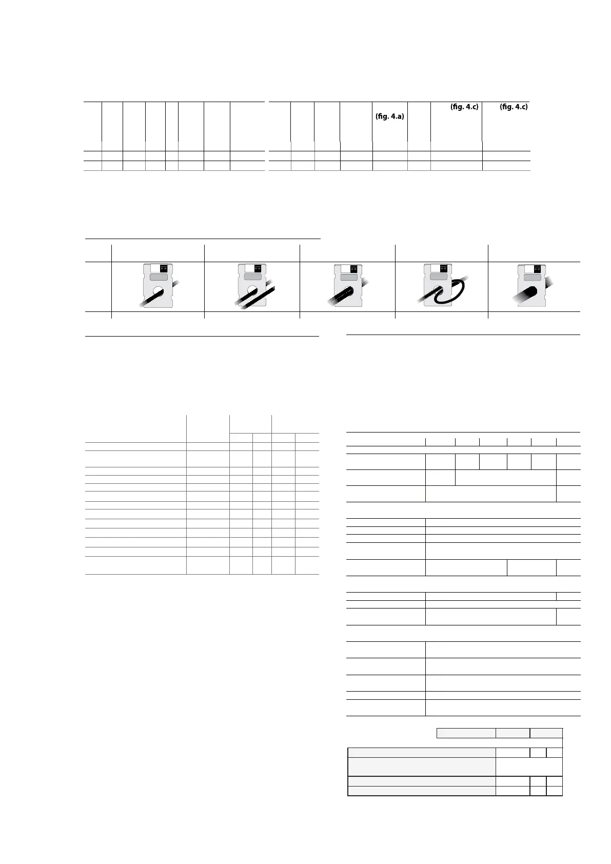
4.2 TAM (current transformer)
congurations
one cable turn one of two cables
of the same phase
two cables of the same phase one cable
on “bouble turn” mode
three cable turns
of the same phase
CPY*
700
500
300
100
C
700
500
300
100
700
500
300
100
700
500
300
100
700
500
300
100
700
500
300
100
C
700
500
300
100
700
500
300
100
C
700
500
300
100
700
500
300
100
700
500
300
100
C
700
500
300
100
700
500
300
100
700
500
300
100
a b c d e
Fig. 4.c
4.3 Supply water
Only use mains drinking water with:
• pressure between 0.1 and 0.8 MPa (1 and 8 bars), temperature between
1 and 40 °C and an instant flow-rate no lower than the rated flow of the
fill solenoid valve, the connection is G 3/4’’ M;
• hardness no greater than 400 ppm of CaCO3 (40 °fH), conductivity
range: 75-1250 µS/cm;
• no organic compounds.
supply water characteristics unit of
measure
normal
water
water with low
salt content
min. max. min. max.
Hydrogen ions (pH) 7 8,5 7 8,5
Specific conductivity
at 20 °C (σR, 20 °C)
µS/cm 350 1250 75 350
Total dissolved solids (TDS) mg/l (1) (1) (1) (1)
Dry residue at 180°C (R180) mg/l (1) (1) (1) (1)
Total hardness (TH) mg/l CaCO3 100 (2) 400 50 (2) 160
Temporary hardness mg/l CaCO3 60 (3) 300 30 (3) 100
Iron + Manganese mg/l Fe+Mn 0 0,2 0 0,2
Chlorides
ppm Cl- 0 30 0 20
Silica
mg/l SiO2 0 20 0 20
Residual chlorine
mg/l Cl2 0 0,2 0 0,2
Calcium sulphate
mg/l CaSO4 0 100 0 60
Metallic impurities
mg/l 0 0 0 0
Solvents, thinners, detergents,
lubricants
mg/l 0 0 0 0
Tab. 4.b
(1)
= values depend on the specific conductivity; in general:
TDS ≅0,93 * σ
R, 20 °C
; R
180
≅0,65 * σ
R, 20 °C
(2)
= not less than 200% of the chloride content in mg/l CL
-
(3)
= not less than 300% of the chloride content in mg/l CL
-
There is not reliable relationship between hardness and conductivity of
the water.
Important:
• do not treat the water with softeners, this may cause the entrainment
of foam, affecting the operation of the unit;
• do not add disinfectants or anticorrosive compounds to the water, as
these are potential irritants;
• the use of well water, industrial water or water from cooling circuits
and, in general, any potentially chemically or bacteriologically
contaminated water is not recommended.
3 KUECP, CPY, PCO3: Hardware configuration
14
ENG
“OEM KUE” +030222130 - rel. 1.3 - 12.03.2015
4.4 Drain water
• this contains the same substances dissolved in the supply water,
however in larger quantities;
• it may reach a temperature of 100 °C;
• it is not toxic and can be drained into the sewerage system, category
3, EN 1717.
4.5 Technical specications
KUE*(R, 1)*
KUES2* KUET2* KUES3* KUET3* KUET4*
Steam:
flow-rate kg/h (lbs/hr)
1,5...3
(3..3/6.6)
5 (11) 5...8
(11/17.6)
9 (19.8) 10...15 25...45
connection: D mm (‘‘)
23/30
(0.9/1.2)
30 (1.2) 40
outlet pressure limits
(Pa/PSI)
0...500 (0...0.072) 0...2300
Supply water:
connection
G 3/4’’ M
temperature limits (°C/°F)
1...40 (33.8...104)
pressure limits
0,1...0,8 (1...8 BAR, 14.5...116 PSI)
hardness limits ppm
CaCO3(°fH)
≤ 400 (40)
instant flow-rate l/min
(gal/hr)
0,6 (9,5) 1,2 (19) 4
Drain water:
connection: D mm (‘‘)
32 (1.2) 40
typical temperature (°C/°F)
≤ 100 (212)
instant flow-rate I/min
(gal/hr)
10 (159) 22,5
Environmental conditions:
ambient operating
temperature (°C/°F)
1...50 (33.8...122)
ambient operating
humidity (% rH)
10...90 (non condensante)
storage temperature
(°C/°F)
-10T70 (14T158)
storage humidity (% rH)
5...95
index of protection
(IEC EN 60529)
IP00
Tab. 4.c
4.2 TAM (current transformer)
congurations
one cable turn one of two cables
of the same phase
two cables of the same phase one cable
on “bouble turn” mode
three cable turns
of the same phase
CPY*
700
500
300
100
C
700
500
300
100
700
500
300
100
700
500
300
100
700
500
300
100
700
500
300
100
C
700
500
300
100
700
500
300
100
700
500
300
100
C
700
500
300
100
700
500
300
100
700
500
300
100
700
500
300
100
C
700
500
300
100
700
500
300
100
700
500
300
100
700
500
300
100
700
500
300
100
a b c d e
Fig. 4.c
4.3 Supply water
Only use mains drinking water with:
• pressure between 0.1 and 0.8 MPa (1 and 8 bars), temperature between
1 and 40 °C and an instant flow-rate no lower than the rated flow of the
fill solenoid valve, the connection is G 3/4’’ M;
• hardness no greater than 400 ppm of CaCO3 (40 °fH), conductivity
range: 75-1250 µS/cm;
• no organic compounds.
supply water characteristics unit of
measure
normal
water
water with low
salt content
min. max. min. max.
Hydrogen ions (pH) 7 8,5 7 8,5
Specific conductivity
at 20 °C (σR, 20 °C)
µS/cm 350 1250 75 350
Total dissolved solids (TDS) mg/l (1) (1) (1) (1)
Dry residue at 180°C (R180) mg/l (1) (1) (1) (1)
Total hardness (TH) mg/l CaCO3 100 (2) 400 50 (2) 160
Temporary hardness mg/l CaCO3 60 (3) 300 30 (3) 100
Iron + Manganese mg/l Fe+Mn 0 0,2 0 0,2
Chlorides
ppm Cl- 0 30 0 20
Silica
mg/l SiO2 0 20 0 20
Residual chlorine
mg/l Cl2 0 0,2 0 0,2
Calcium sulphate
mg/l CaSO4 0 100 0 60
Metallic impurities
mg/l 0 0 0 0
Solvents, thinners, detergents,
lubricants
mg/l 0 0 0 0
Tab. 4.b
(1)
= values depend on the specific conductivity; in general:
TDS ≅0,93 * σ
R, 20 °C
; R
180
≅0,65 * σ
R, 20 °C
(2)
= not less than 200% of the chloride content in mg/l CL
-
(3)
= not less than 300% of the chloride content in mg/l CL
-
There is not reliable relationship between hardness and conductivity of
the water.
Important:
• do not treat the water with softeners, this may cause the entrainment
of foam, affecting the operation of the unit;
• do not add disinfectants or anticorrosive compounds to the water, as
these are potential irritants;
• the use of well water, industrial water or water from cooling circuits
and, in general, any potentially chemically or bacteriologically
contaminated water is not recommended.
3.1
3.2
3.3
3.4
OEM
Code CAREL +030221793 - Rel. 2.5 02/02/11
35
8. TECHNISCHE DATEN
MODELL
KUET1* KUET2*
Dampf
Leistung (kg/h) 1,5...3 5...8
22/30
0...500
G¾
1...40
0,1...0,8 (1...8bar, 14,5...116PSI)
≤ 40
32
≤ 100
~ 4
1...50
10...60 (90 nicht kondensierend)
-10T70
5...95
IP00
24 VAC (-15%...+10%) / 50...60Hz
125...1250
0,6
30
Anschluss φ (mm)
Grenzwerte des Zuluftdrucks (Pa)
Speisewasser
Anschluss
Temperaturgrenzwerte (°C)
Druckgrenzwerte (MPa)
Wasserhärtegrenzwerte (°fH)
Durchfluss (l/min)
Leitfähigkeit (µS/cm)
Abschlämmwasser
Anschluss φ (mm)
Typische Temperatur (°C)
Durchfluss (l/min)
Umgebungsbedingungen
Betriebstemperatur (°C)
Betriebsfeuchtigkeit (% r.F.)
Lagerungstemperatur (°C)
Lagerungsfeuchtigkeit (% .F.)
Schutzart (CEI EN 60529)
Elektronischer Regler (siehe Anleitungen des CP-Reglers
Typ
CP3*
5 8
3,75
3
2,25 6,00
30
Spannung / Frequenz Hilfsschaltkreise (V - Hz)
Max. Leistung Hilfsschaltkreise (VA)
Fühlereingang
Eingangsimpedanz Spannungs-
signal 0...10 V, 2...10 V, 0...1 V: 15 kΩ
Elektrische Daten: siehe Anleitungen des CP-Reglers Code +050003765
MODEL
KUET1* KUET2*
Power consumption
8 5 3
Flow rate (kg/h)
(1)
Power consumption at rated voltage (kW)
Rated voltage:
400V-3 ~ Code L
CAREL behält sich das Recht vor, an den eigenen Produkte