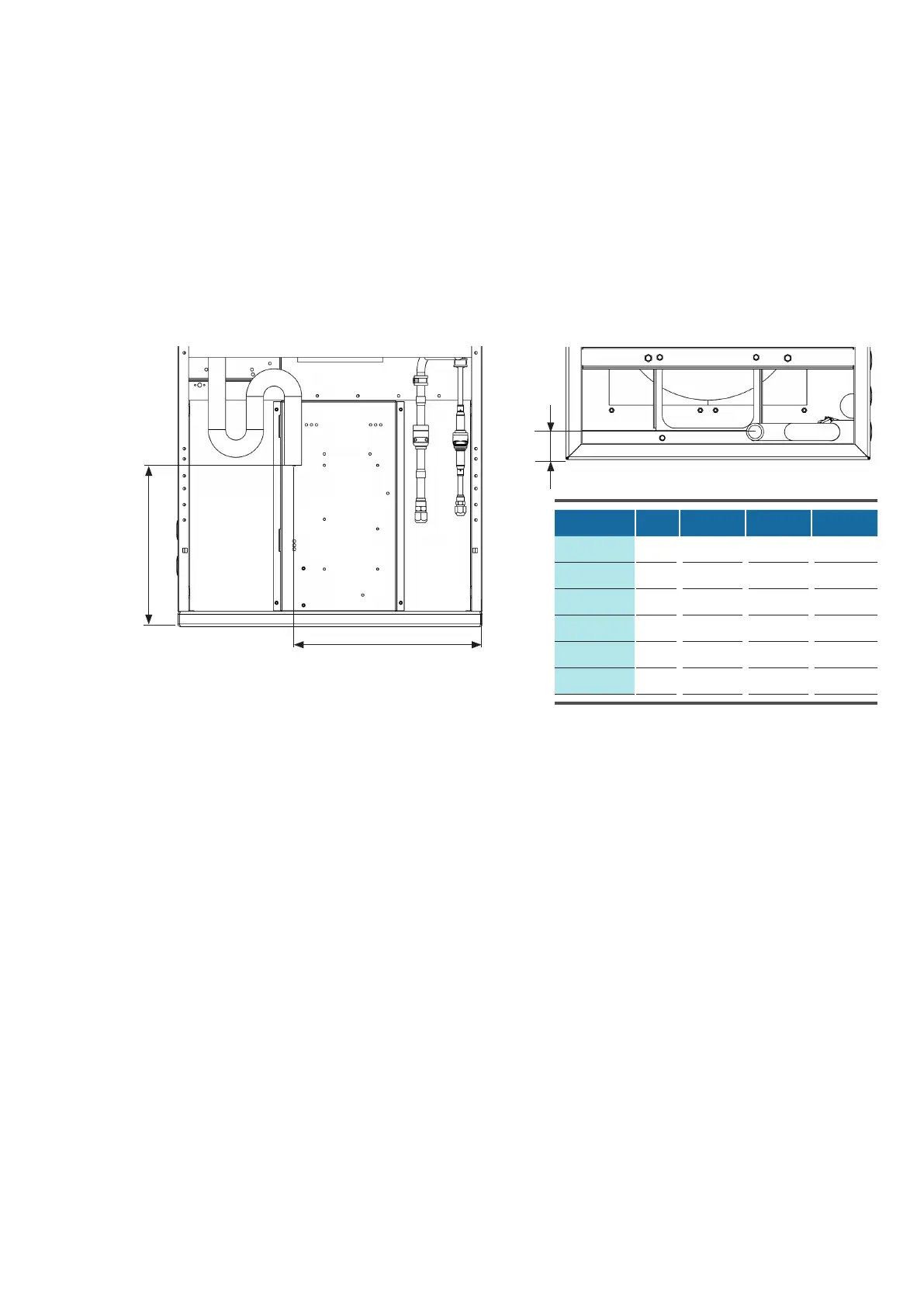
43
Unit Cx Cy Cz
ECD 91
mm 373 317 55
ECU 91
mm 373 266 54
ECD 181
mm 775 320 53
ECU 181
mm 532 106 84
ECD 251
mm 775 320 55
ECU 251
mm 539 108 84
© STULZ GmbH – all rights reserved EN/01.2019/G22
EC TOWER TECHNICAL MANUAL
Free condensate drainage via condensate pipe and drainage pipe
The diagrams below show the dimensions of the condensate drain.
EC Tower - View from rear: EC Tower - View from below:
Cy
Cx
Cz
The diagrams below show the components of the condensate drain. In all EC Towers, the drain is situated at
the rear right. The drainage pipe may be routed through a hole in the left or right-hand side panel, depending
on local circumstances. The diagram below shows the drainage pipe installation with hole in the right-hand
side panel.
Components colored gray are not included with the EC Tower, and must be provided by the customer.
included with the EC Tower, and must be provided by the customer.
Installation of the hot water condensate pump is described in section: “13.2Installing the condensate pump“
on page 78.