85 © STULZ GmbH – all rights reserved EN/01.2019/G22
ec tower technical manual
Procedure
1. Connect the condensate pump as per the circuit diagram.
- Connect the live wire of the condensate pump to the control fuse (F10) at terminal (2) in junction box 1.
- Connect the neutral wire of the condensate pump to terminal (X1/N5) in junction box 1.
- For size 2: Connect the PE conductor of the condensate pump to terminal (X0/PE6).
2. Remove the bridge from terminals (X4/3) and (X4/4) in junction box 2.
3. Connect fault signaling contact 1 of condensate pump to terminal (X4/3) in junction box 2.
4. Connect fault signaling contact 2 of the condensate pump to terminal (X4/4) in junction box 2.
Testing the condensate pump
CPY
c
o
nt
r
o
ller
CAREL
M8 M5M2M1
M12
J1
M6 M10
M11
M7
M9M3
M14
2
2
1
2
1
2
1
2
3
1
2
3
2
1
1
1
2
3
1
2
3 4 5 6 7
2
3
1
2
JS6
1
HCT
1
2
M2M1
M12
1
2
3
1
2
3 4 5 6 7
HCT
1
2
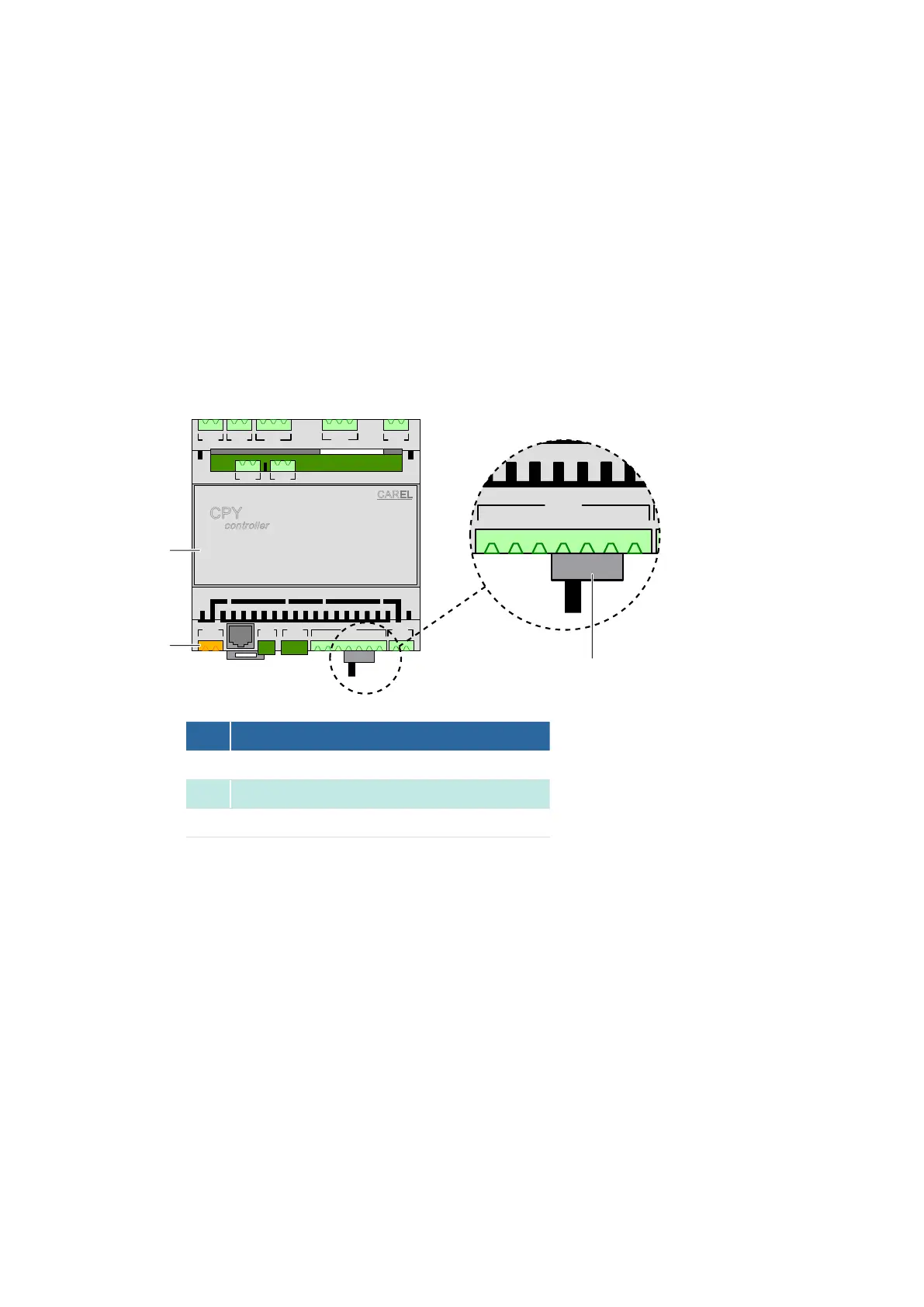
No. Description
1
CPY controller of humidifier
2
Switch S70 for manually draining the steam humidifier
3
Terminal M8 for the CPY controller power supply
2
3
1
Procedure
1. Turn on the water supply to the steam humidifier.
2. S70) on the CPY controller to the left (M24 ON/OFF).
- The steam humidifier goes into normal operation.
3. Fit the right-hand cover panel.
4. Fit the lower front panel.
5. Fit the central protective grill.
6. Close the door of junction box 1 using the supplied triangular socket wrench.
7. Switch on the unit via the master switch.
8.