Before starting measurements, the instrument should be
calibrated using the recommended sound calibrator (see
Chapter 3.2).
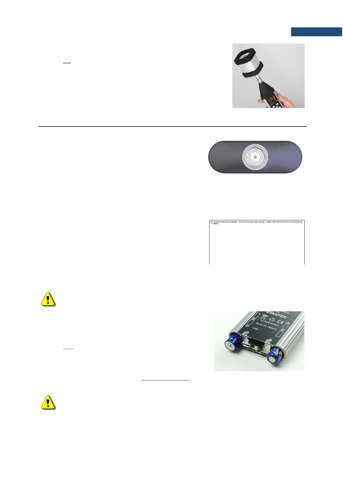
2.2 INPUT AND OUTPUT SOCKETS OF THE INSTRUMENT
Top cover of the instrument
The measurement Input is placed in the centre of the
instrument’s top cover. The SV 18A microphone preamplifier
has a specially designed matching plug with a locking screw
to secure the preamplifier to the meter body. After plugging in
the preamplifier to the measurement input, the screw should
be tightened to light resistance only. Do not over tighten this
connector. It is not necessary to remove this preamplifier from
the top of the instrument unless the meter is in a calibration
laboratory as it is always used close coupled to the meter
body. The full description of the signals connected to the
sockets is given in Appendix C.
Bottom cover of the instrument
In the bottom cover, there is only one socket – USB (C type).
The USB-C Device 2.0 interface is the serial interface working with 12 MHz clock in the full speed mode
and with 480 MHz in the high-speed mode, which is a default mode of the instrument. The USB-C socket
is described in detail in Appendix C.
Note: Switch the power off before connecting the instrument to any other device (e.g. a printer
or a Personal Computer) or fitting the microphone capsule.
There is a memory micro SD-card slot under the bottom cover
of the instrument and spaces for the 4 x AAA batteries.
You can access the card and batteries by unscrewing the coin
slot screw and removing the bottom cover – see
Chapter 16.1.
Note: The originally supplied Kingston Industrial memory card has been tested by SVANTEK
and cards of this type are strongly recommended for use when the original card is going to be
replaced.