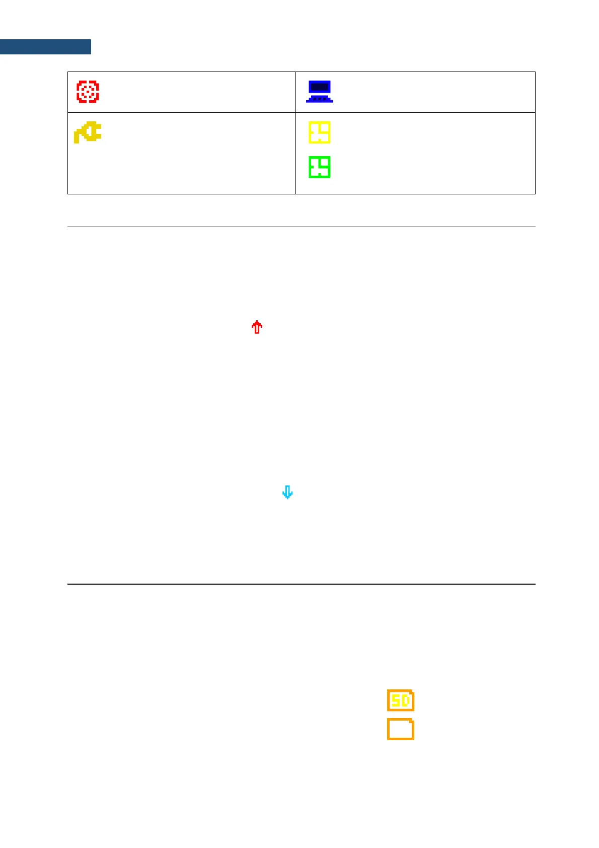
“vibration” icon is displayed when high
self-vibration level is registered
“USB” icon is displayed when there is
USB connection with the PC.
“plug” icon is displayed when the
instrument is powered through the USB
socket without using USB interface.
“clock” icon is displayed when the timer
is On. It is active when the instrument is
waiting for the measurement start to
occur. When the measurement start is
close, the icon changes its colour to green
and start blinking.
2.8 OVERLOAD AND UNDERRANGE DETECTION
Overload detector
The instrument has the built-in overload detectors. Both A/D converter and input amplifier overload
conditions are detected. The overload in the measurement channel (in its analogue part) and the overload
of the analogue / digital converter are both detected. The “overload” indication appears when the input
signal amplitude is 0.5 dB above the declared “Peak measurement range”. This condition is checked
once per second or with the Logger Step if it is less than 1 second.
An overload is indicating by the flashing icon which is displayed during the period from the overload
detection till the end of the Integration Period. If the overload disappears to the Integration Period end,
the overload icon will not be displayed from the start of the next measurement cycle.
When an overload is detected the special marker will be recorded to the logger file with the data logging
step.
The overload time is measured by the OVL result during the Integration Period and is saved in the logger
file as part of Summary Results.
Underrange detector
The instrument has the built-in underrange detector. The “underrange” indication appears when the RMS
value for the elapsed time is below the lower linear operating range. This condition is checked once per
second.
An underrange is indicating by the flashing icon which is displayed during the period of the
underrange detection. When an underrange is detected till the Integration Period, the special marker will
be recorded to the logger file with the Integration Period step. If during the Integration Period the signal
level increases and the total RMS is greater than the minimum, the icon stops displaying and the
underrange marker is not recording.
The instrument creates files of next types:
• Logger files with measurement results (extension .SVL)
• Wave files with signal recording (extension .WAV)
• Setup files with measurement and instrument configuration (extension .SVT)
Detailed description of structures of all file types is given in Appendix B.
Memory type
All files are stored in the instrument’s memory in the predefined or
assigned directories. The setup files are stored in the predefined
directory SETUP. The non-predefined directories can be changed
by the user or renamed.
The SD Card memory is activated automatically after insertion of
the card. The presence of the SD-card is indicated by the icon with
SD letters at the top left-hand corner of the display.
- SD-card is inserted
- no SD-card