Triggering
3-64
CSA7000B Series & TDS7000B Series Instruments User Manual
Triggering Concepts
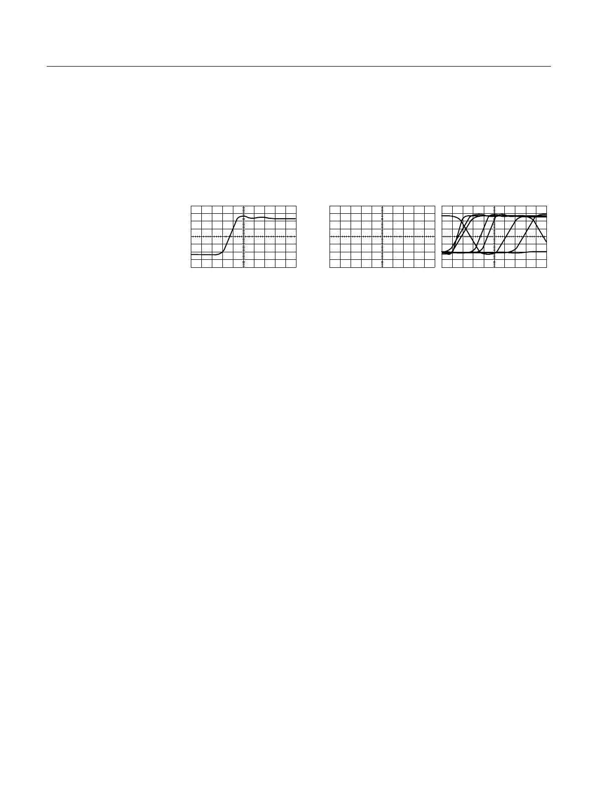
Triggers determine when the instrument stops acquiring and displays a wave-
form. They help create meaningful waveforms from unstable jumbles or blank
screens. (See Figure 3--21. ) The instrument has simple edge triggers as well as a
variety of advanced triggers you can use.
Triggered waveform Untriggered waveforms
Figure 3- 21: Triggered versus untriggered displays
The trigger event establishes the time-zero point in the waveform record. All
points in the record are located in time with respect to that point. The instrument
continuously acquires and retains enough sample points to fill the pretrigger
portion of the waveform record (that part of the waveform that is displayed
before, or to the left of, the triggering event on screen). When a trigger event
occurs, the instrument starts acquiring samples to build the posttrigger portion of
the waveform record (displayed after, or to the right of, the trigger event). Once a
trigger is recognized, the instrument will not accept another trigger until the
acquisition is complete and the holdoff time has expired.
The trigger source provides the signal that triggers acquisition. Use a trigger
source that is synchronized with the signal you are acquiring and displaying. You
can derive your trigger from the following sources:
H Input channels are the most commonly used trigger sources. You can select
any one of the four input channels. The channel that you select as a trigger
source will function whether it is displayed or not.
H AC Line Voltage is a convenient trigger source when you are looking at
signals related to the power line frequency. Examples include devices such as
lighting equipment and power supplies. Because the instrument generates the
trigger from the power line, you do not have to use a channel input.
H Auxiliary Trigger (AUX IN) provides a fifth source that you can use as a
trigger input when you need to use the four input channels for other signals.
For example, you might want to trigger on a clock while displaying four
other logic signals. To use the auxiliary trigger, connect the signal to the
Auxiliary Trigger input connector. The Auxiliary Trigger input is not
compatible with most probes, nor can you display the auxiliary trigger
signal.
The Trigger Event
Trigger Sources