Triggering
CSA7000B Series & TDS7000B Series Instruments User Manual
3-67
Indicates trigger points
Trigger level
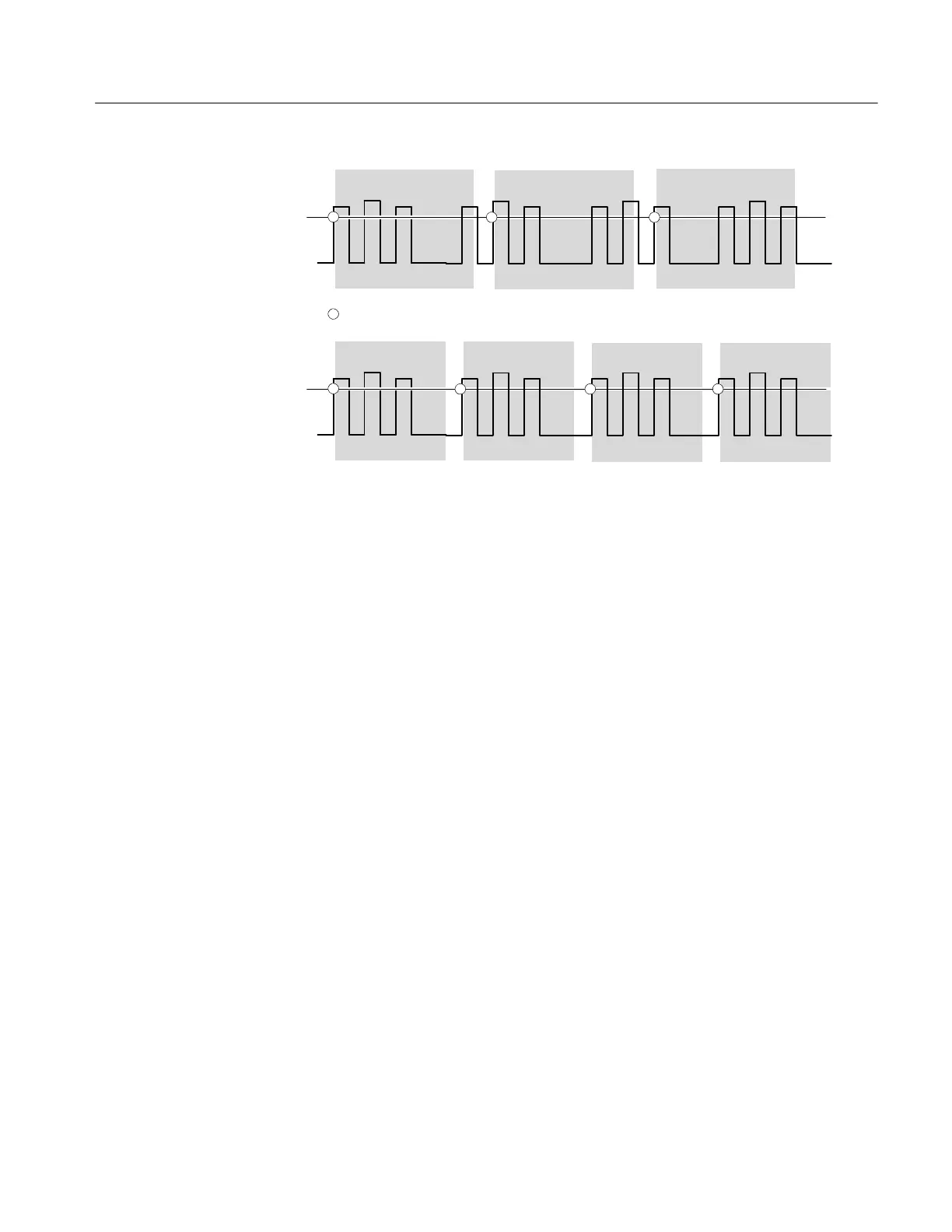
At the longer holdoff time for the top waveform, unstable triggering occurs. With a shorter holdoff set for
the bottom waveform, triggers all occur on the first pulse in the burst to remedy the unstable trigger.
Holdoff Holdoff Holdoff
Trigger level
Holdoff Holdoff Holdoff Holdoff
Figure 3- 23: Holdoff adjustment can prevent f alse triggers
Trigger coupling determines what part of the signal is passed to the trigger
circuit. Edge triggering can use all available coupling types: AC, DC, Low
Frequency Rejection, High Frequency Rejection, and Noise Rejection. All the
advanced trigger types use only DC coupling. See To set the trigger coupling on
page 3--71 for a description of each coupling type.
Horizontal position is adjustable and defines where on the waveform record the
trigger occurs. It lets you choose how much the instrument acquires before and
after the trigger event. The part of the record that occurs before the trigger is the
pretrigger portion. The part that occurs after the trigger is the posttrigger portion.
When horizontal delay is off, the reference marker shows the trigger position in
the waveform.
Displaying pretrigger information can be valuable when troubleshooting. For
example, if you are trying to find the cause of an unwanted glitch in your test
circuit, you can trigger on the glitch and make the pretrigger period large enough
to capture data before the glitch. By analyzing what happened before the glitch,
you may uncover clues about its source.
The slope control determines whether the instrument finds the trigger point on
the rising or the falling edge of a signal. (See Figure 3--24.)
Trigger Coupling
Horizontal Position
Slope and Level